
Injection-molding device for manufacturing V-engine blocks

a technology of injection molding and v-engine, which is applied in the direction of manufacturing tools, mechanical equipment, cylinders, etc., can solve the problems of large mass moving in the injection molding machine, and achieve the effect of reducing mass and overall height, and stable mounting of the mold

Inactive Publication Date: 2009-03-10
BUHLER DRUCKGASS AG
View PDF3 Cites 8 Cited by
  • Summary
  • Abstract
  • Description
  • Claims
  • Application Information

AI Technical Summary

Benefits of technology

"The invention is a new injection-molding device for making V-engine blocks that solves the problems of previous methods. It has a stable mounting system and is much lighter and flatter. The device is modular and can be used for all types of V-blocks. The center sleeve sliders are only supported in the mounting plate and not connected with it, and the ejection device is integrated in the mold plate. Overall, this device reduces the mass and overall height of the mold by at least 20%."

Problems solved by technology

The described molds are structurally complex, so that very large masses have to be moved in the injection-molding machine.

Method used


Image

  • Injection-molding device for manufacturing V-engine blocks
  • Injection-molding device for manufacturing V-engine blocks
  • Injection-molding device for manufacturing V-engine blocks

Examples


Embodiment Construction

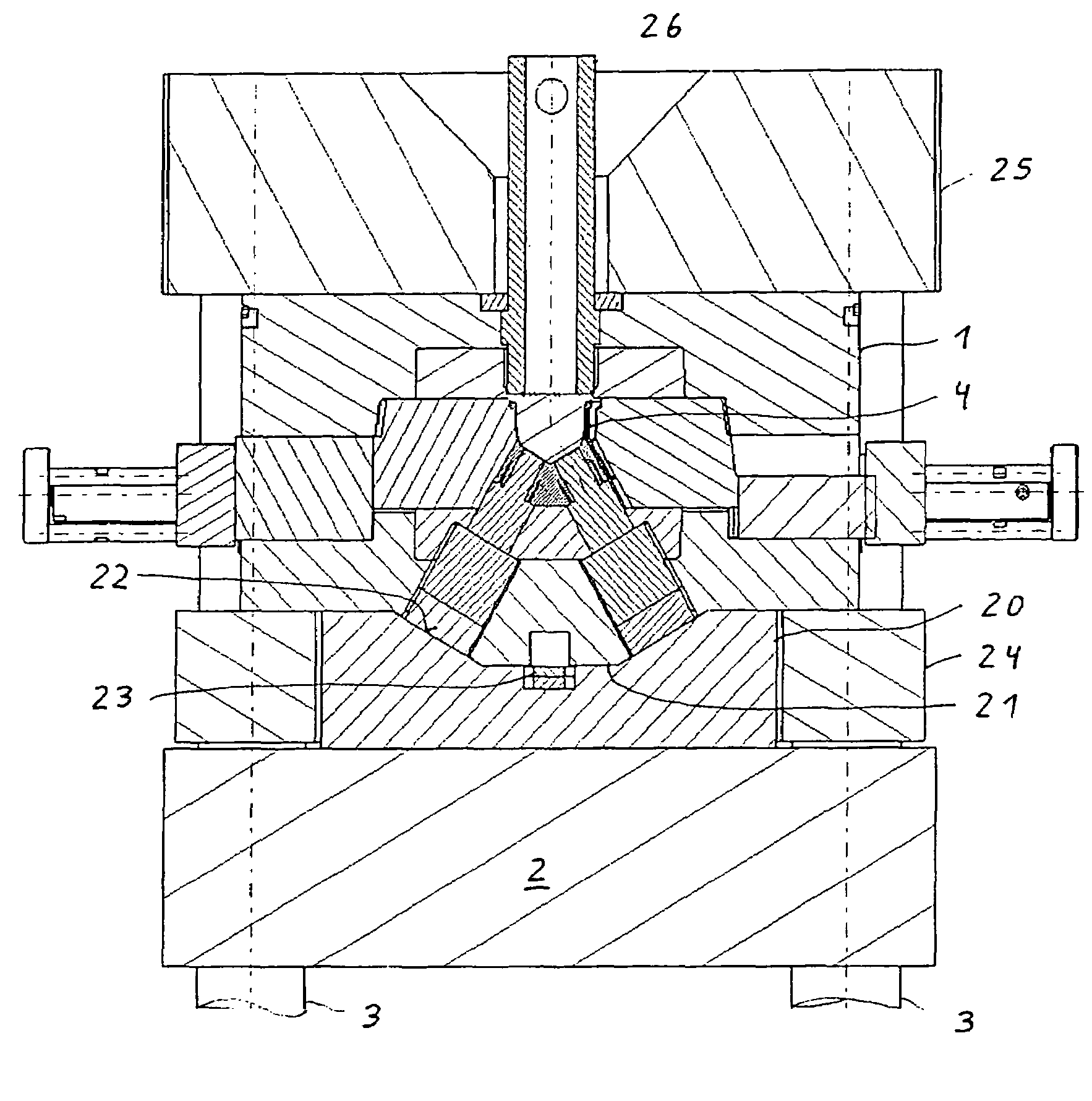
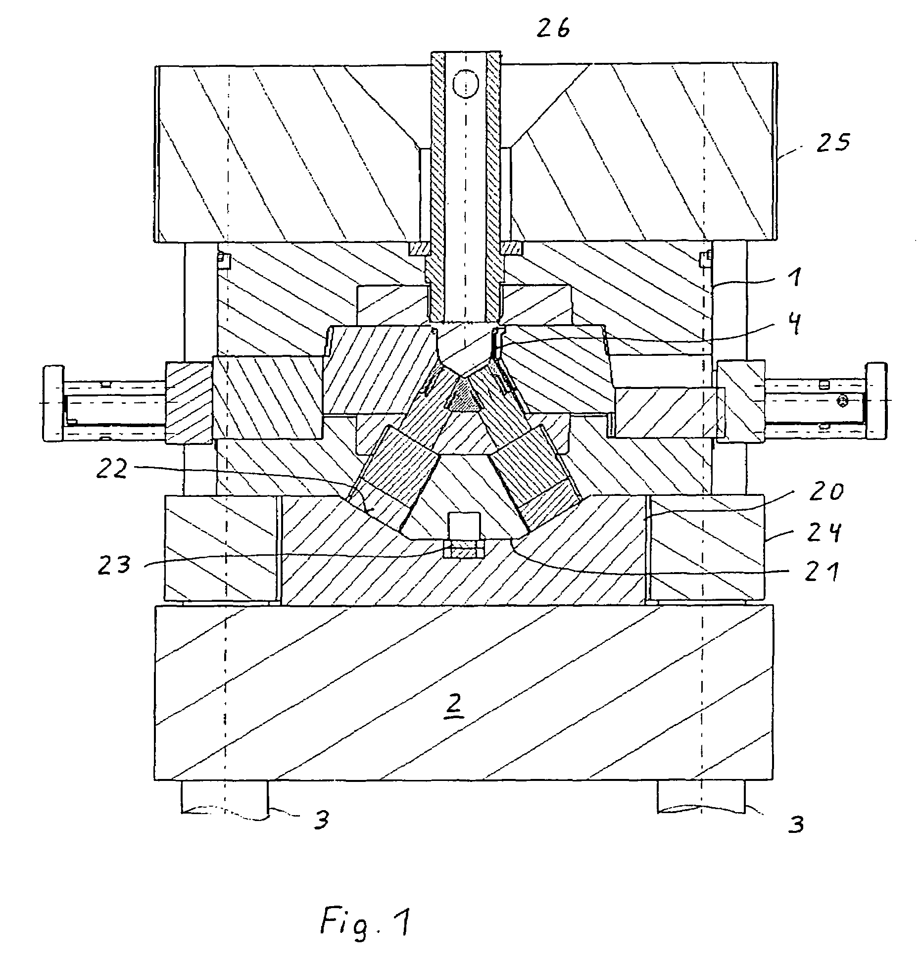
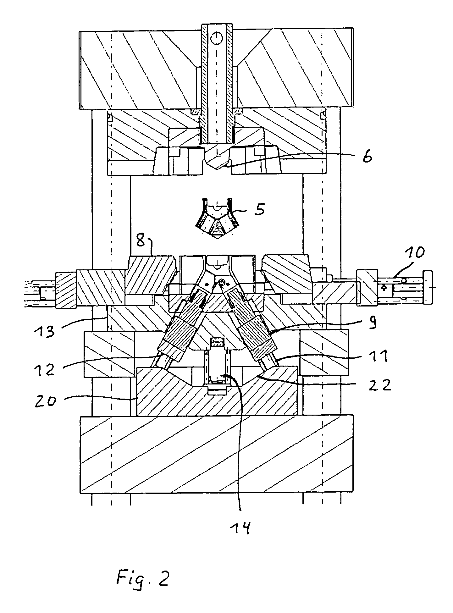
[0015]An injection-molding device, an injection-molding machine for manufacturing V6N8N10N12 engine blocks 5 in the example (not explicitly shown), contains a fixed mold half 1 and a moving mold half 13, wherein the moving mold half 13 is mounted on a moving and guided mounting frame 24. The mold cavity 4 for the V-engine block 5 is bordered by an insert 6 in the fixed mold half 1, an insert 7 in the moving mold half 13, as well as lateral sliders 8 and center sleeve sliders 9, wherein the latter angularly correspond to the V-shape of the engine block. The sliders 8 or center sleeve sliders 9 are actuated by 2-way hydraulic cylinders 10, 11.

[0016]The sliders 8 can be used to minimize changes in location and position owing to casting technique. As disclosed in DE 101 28874 A 1, this is achieved by providing surfaces for locking a slider 8 and additional surfaces for the combined counter-locking and mold centering on mold frames 13 along with molded parts or sliders 8.

[0017]A supporti...


PUM

PropertyMeasurementUnit
forceaaaaaaaaaa
bursting forceaaaaaaaaaa
oblique angleaaaaaaaaaa

Abstract

An injection-molding device is for manufacturing V-engine blocks, in particular an injection-molding machine with a fixed and moving mold half, wherein the moving mold frame contains sliders and ejectors, along with center sleeve sliders angularly arranged relative to each other and a supporting plate for locking the center sleeve slider. Therefore, the force is introduced perpendicular via the center sleeve sliders, and absorbed via the supporting plate or moving identification plate. The moving mold half is secured on a mounting frame.

Description

BACKGROUND OF THE INVENTION[0001]The invention relates to an injection-molding device for manufacturing V-engine blocks for combustion engines. In particular, the injection-molding device is an injectionmolding machine with the corresponding mold.[0002]U.S. Pat. No. 5,865,241 discloses an injection-molding machine for manufacturing V-engine blocks in a mold with a fixed and moving mold half. In addition to the mold cavity, the moving mold half encompasses a column-guided ejector unit. A mounting plate accommodates an ejector box that can be lifted from it by means of a dual-action cylinder. The cylinder extends over the side of the mounting plate facing away from the mold.[0003]Additional cylinders used for inserting and removing sliders are bilaterally situated perpendicular to this cylinder at the level of the mold cavity.[0004]The ejector box is a massive plate that occupies a portion of the initially mentioned cylinder, and has a trapezoidal cross-section. The inclined lateral w...

Claims


Application Information

Patent Timeline
Patent Type & Authority Patents(United States)
IPC IPC(8): B22D17/26B22D33/04
CPCB22D17/24B22D19/0009B22D17/20B22D17/26B22D19/00
Inventor HEINRICH, SIEGFRIEDPADOVAN, SASCHABINDER, ULRICHNIEDERMANN, BENNO
Owner BUHLER DRUCKGASS AG
Learn More