
Contour reading device comprising a force sensor

a reading device and force sensor technology, applied in the field of dimension measurement devices, can solve the problems of not being able to guarantee the finger's position in the bottom of the bezel, and the finger's bottom being difficult to remain in the bezel, so as to achieve the effect of simple and convenient us

Inactive Publication Date: 2009-03-10
ESSILOR INT CIE GEN DOPTIQUE
View PDF12 Cites 12 Cited by
  • Summary
  • Abstract
  • Description
  • Claims
  • Application Information

AI Technical Summary

Benefits of technology

[0014]The object of the invention is to provide a contour reading method for alleviating the drawbacks mentioned above at the same time as being particularly simple and convenient to use. Another object of the invention is to propose a reading device adapted to any type of contour suitable for the implementation of a method of this kind.
[0016]Accordingly, the finger is at all times at a distance from the rotary platform corresponding to a particular force exerted by the article to be read on the feeler, which enables the finger to follow a predetermined path and in particular prevents the finger from dropping off the contour. Moreover, the force is measured in only one direction, which simplifies measurement.
[0018]The position of the member relative to the rod enables use of the relatively large receiving space available under the platform. Moreover, the force sensor being away from the finger in this receiving space, it is rendered inaccessible from the outside so that it is protected from unintentional misadjustment by the user or from dust.

Problems solved by technology

On the other hand, in the case of frame rims with highly curved portions, where the amplitude along the axis (z) is therefore high, the free movement of the finger along the axis (z) makes it more difficult for the finger to remain in the bottom of the bezel.
The feeler is guided as it follows the contour but there is nothing to guarantee that the finger will remain in the bottom of the bezel.

Method used


Image

  • Contour reading device comprising a force sensor
  • Contour reading device comprising a force sensor
  • Contour reading device comprising a force sensor

Examples


Embodiment Construction

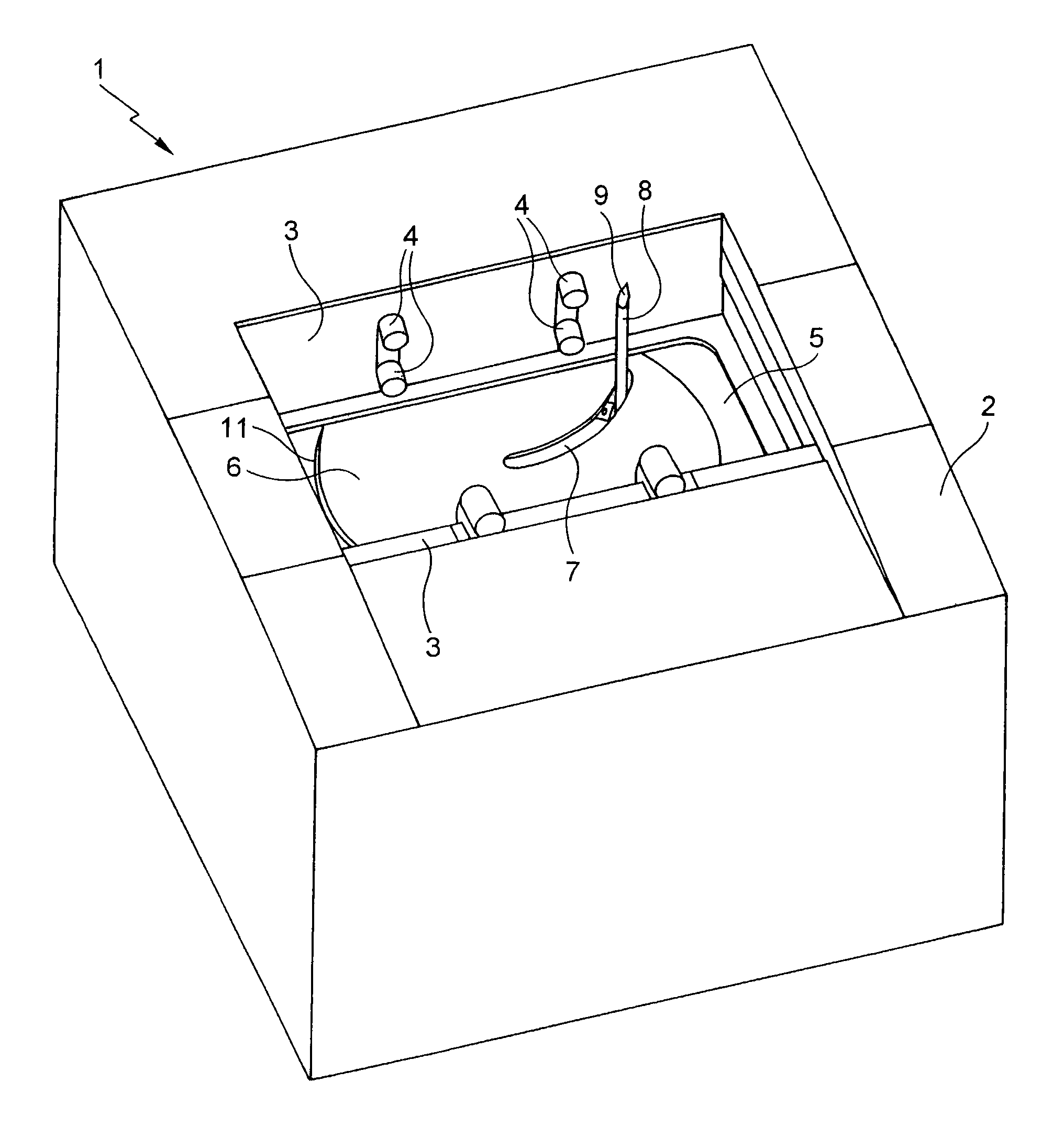
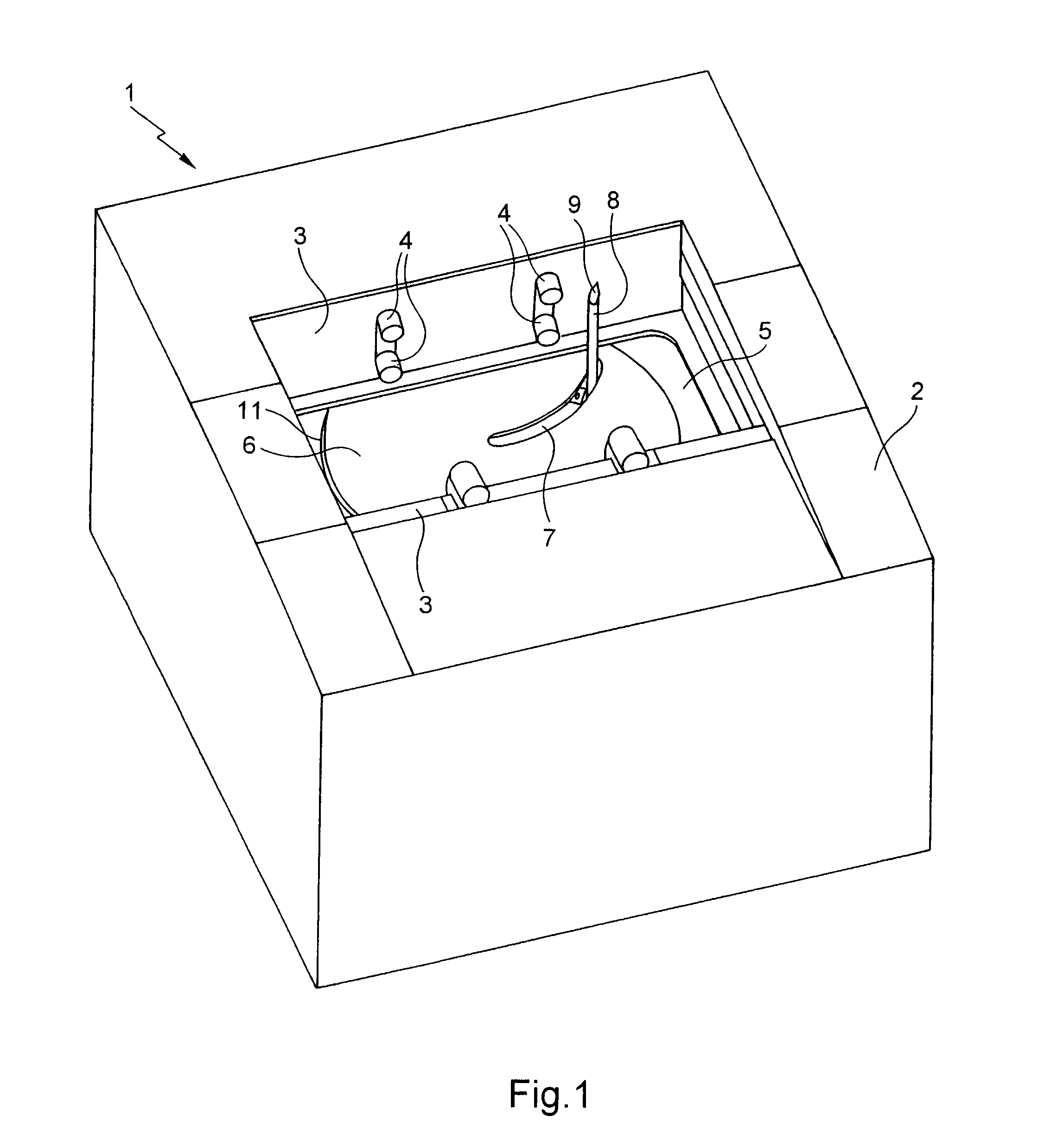
[0046]FIG. 1 is a general view of a contour reading device 1 as seen by its user. This device 1 includes an upper cover 2 covering the whole of the device except for an upper central portion.

[0047]A rotary platform 6 is mounted to rotate relative to the chassis 5 of the device 1. This rotary platform 6 includes an oblong opening 7 of circular arc shape through which projects a feeler 8 including a rod 12 provided at its distal end with a finger 9.

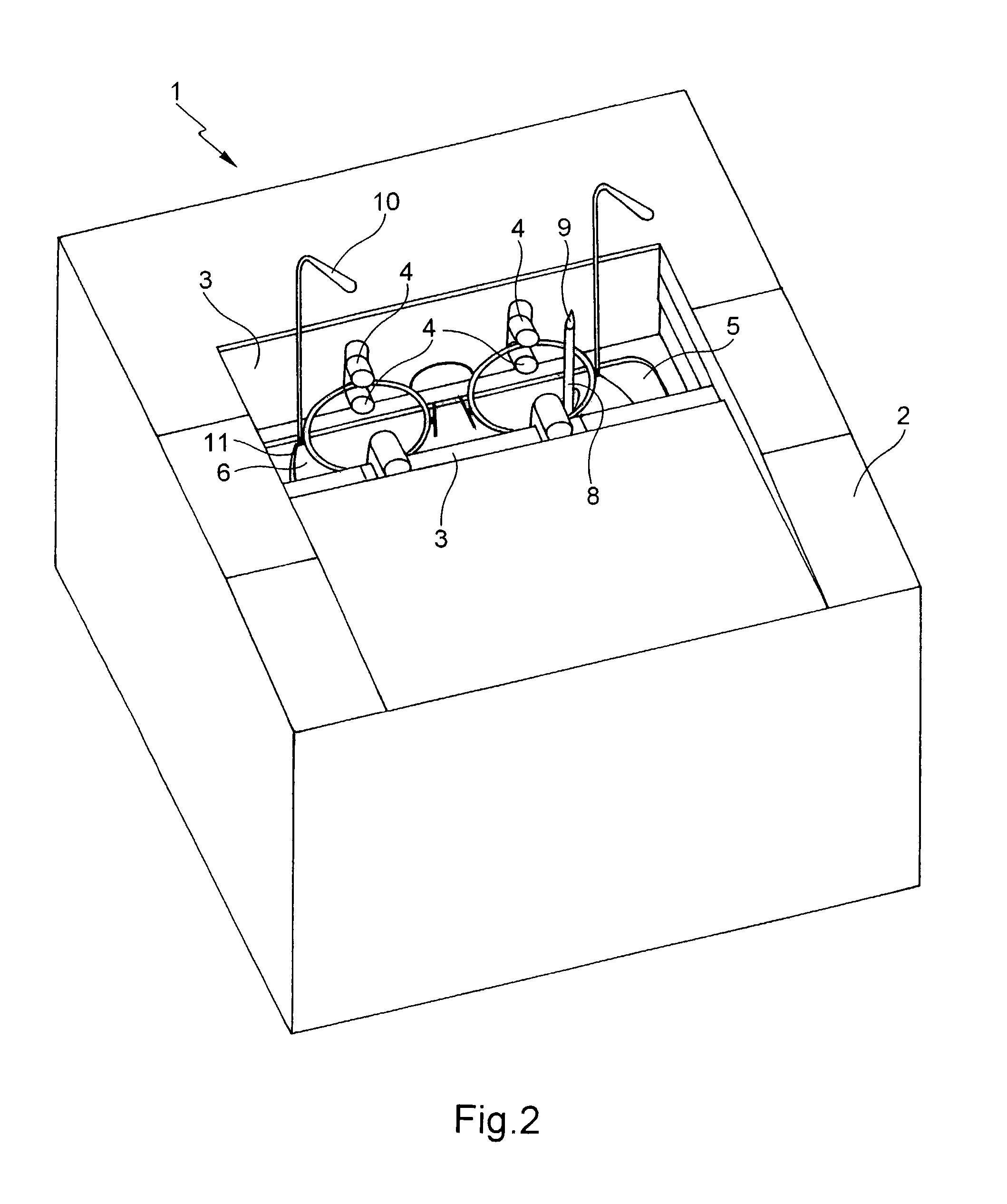
[0048]The device 1 from FIG. 1 is intended to receive a frame 10.

[0049]As seen in FIG. 2, the device 1 includes a device for gripping the frame 10 featuring two parallel jaws 3 and four clamps. Each clamp includes two studs 4 and is situated on one jaw 3 facing a clamp of the other jaw 3.

[0050]At least one of the jaws 3 is adapted to move towards or away from the other one to grip the frame 10. In the position with the frame 10 gripped, the clamps are situated face-to-face on each rim, in a direction that corresponds to a vertical direction...


PUM


Abstract

A contour reading method for an item such as an eyewire for spectacles, the method using an appliance including a support for holding the item, and a rotary platform which is rotatably mounted in relation to the support about a rotational axis and carries a reading sub-set provided with a sensor consisting of a finger and a rod, the finger having a distal end. The distal end is displaced along the contour and successive positions thereof are detected. The method is characterized in that the displacement step includes a measuring step wherein the effort exerted between the platform and the rod is measured parallel to the rod, and a control step wherein the distance between the finger and the platform is controlled according to the effort in such a way that the intensity of the effort remains lower than a pre-determined threshold.

Description

FIELD OF THE INVENTION[0001]The invention relates to the general field of dimensional measurement devices used in the fabrication of eyeglasses adapted to a particular wearer.[0002]The invention relates more particularly to a contour reading method and a contour reading device adapted, with the aid of a feeler, to determine the shape of an article disposed on a support. The palpated article is generally an eyeglass frame rim or an ophthalmic lens.BACKGROUND OF THE INVENTION[0003]A device of this kind is used, for example, to determine the shape of the bezel of a frame rim, i.e. the groove that runs around the interior of the frame rim and retains an ophthalmic lens in the frame rim. To this end, the feeler is inserted into the bezel and follows the contour of the bezel while the device measures the coordinates of the position of the feeler along its path, thereby storing a digital image of the contour of the bezel. An ophthalmic lens blank can then be trimmed to the dimensions of th...

Claims


Application Information

Patent Timeline
Patent Type & Authority Patents(United States)
IPC IPC(8): G01B5/20G01B7/28B23Q35/12G01B5/004G01B21/20G02C13/00
CPCG01B5/20
Inventor HADDADI, AHMED
Owner ESSILOR INT CIE GEN DOPTIQUE
Learn More