
Firearm magazine

a cartridge magazine and magazine technology, applied in the field of cartridge magazines, can solve the problems of reducing the resistance of the plate to debris intrusion, affecting the sliding ability of the plate, and affecting the design of the magazine, so as to improve the conventional design, the effect of reducing the restriction of opening and loading

Active Publication Date: 2009-03-03
CAMMENGA PROD
View PDF40 Cites 68 Cited by
  • Summary
  • Abstract
  • Description
  • Claims
  • Application Information

AI Technical Summary

Benefits of technology

[0014]In a narrower form, the containing body defines a first cavity and the closure member defines a second cavity that when combined are sufficient to receive and contain the cartridges, but where the first cavity is shorter than a length of the cartridges such that a portion of the bullet extends above the first cavity, which facilitates loading and positioning cartridges in the first cavity prior to closing the cover. In a still narrower form, the containing body and the closure member each have a C-shaped cross section, with the closure member forming at least 10% of the cartridge-storing cavity.
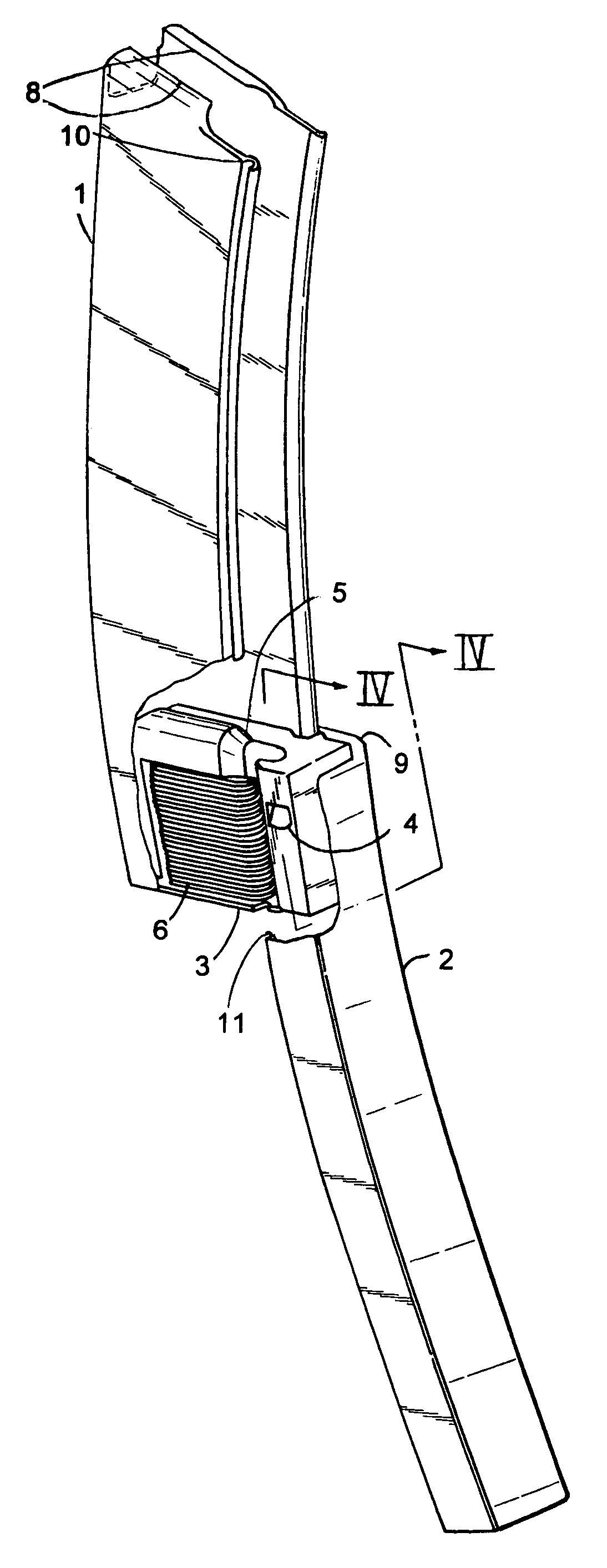
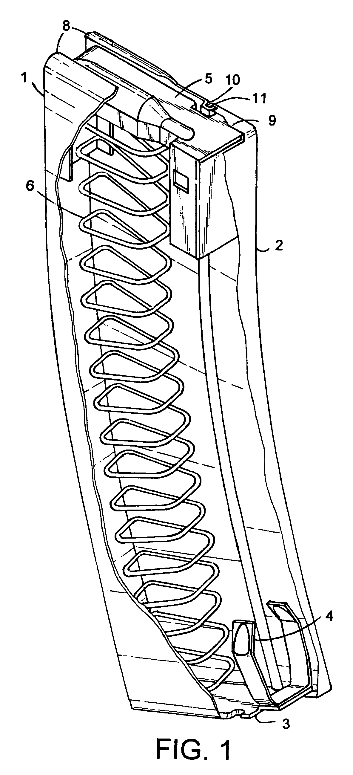
[0017]In another aspect of the present invention, an apparatus includes a magazine with an elongated containing body and a closure member. The closure member is longitudinally slidably mounted on the containing body for telescoping movement between an extended position that opens a side of the containing body to allow cartridges to be loaded into the containing body and a closed position where the cartridges are retained within the containing body. The containing body has an open end adapted to present cartridges to a firearm and has a closed end. A follower is operably mounted in the containing body and includes a shell-engaging member. A spring biases the follower toward the open end of the magazine. The closure member includes a flange for moving the follower toward the closed end when the closure member is moved to the extended position. A latch is positioned within the containing body near the closed end for engaging the follower to hold the follower in a cartridge-loading position with the spring compressed so that cartridges can be loaded without interference from the follower. A release is provided on the closure member that automatically releases the follower and hence allows the spring to expand when the closure member is moved to the closed position so that the follower biases the cartridges in the magazine toward the open end when the closure member is closed.
[0022]This firearm magazine is designed to improve upon the conventional design of a firearm magazine where ammunition is inserted one-by-one through its mouth. In traditional magazines, a spring, opposing the direction of insertion pressure applied, must be depressed in order to insert the ammunition. The opposing pressure of the spring becomes increasingly greater for each inserted round of ammunition. This can cause stress on the fingers of the individual loading the magazine and cause the loading of an entire magazine to become extremely time consuming. It is an object of the present invention to allow for the loading of rounds of ammunition with no resistance from the opposing spring, and a wider, less restrictive opening to insert the ammunition. It also allows for rapid unloading of the ammunition.
[0023]An object of the present invention is to provide an improved, easily-loading, fast-loading, dirt-resistant magazine for firearms, such as automatic and semi-automatic rifles (e.g., Uzi, M16, and AK47 rifles), handguns, and other firearms utilizing a magazine for loading or dispensing ammunition
[0024]Another object of the present invention is to provide for very quick and easy unloading of bullets, such as when a few cartridges remain in the magazine and unloading ammunition, one bullet at a time, is slow, time-consuming, and unnecessarily manually extensive.

Problems solved by technology

However, it includes a slidably mounted latch sensitive to dirt and debris adversely affecting its operation.
The slots are expensive to machine, and further the slots form a narrow track that may trap dirt and debris adversely affecting slidability of the plate, especially when the magazine is being loaded in dirty environments.
Gaidos, like Brown, also discloses an open slot along its length that potentially allows debris to enter the magazine, thus greatly reducing its resistance to intrusion of debris.
Also, a pull ring protrudes from an end of the plate and, along with the latch, is subject to getting caught on objects when manipulating the magazine.
This design is overly complex and uses many extra parts that would be cumbersome to carry or use.
The process needed to load a magazine with this design is also more tedious than the conventional one-by-one loading method.
This design requires a multitude of heavy parts for its construction.
The design of this loader is bulky, overweight, and is far from portable.
It also does not allow for the loading of a magazine where the ammunition is inserted on an angle, such as most semi-automatic handgun magazines.
This concept arguably offers no real advantage to loading a magazine.
The cord and ring could easily be caught on objects while the magazine is dispensing the ammunition into the firearm, hence jeopardizing the critical function of the magazine's dispensing action.
The cord also has the possibility of becoming tangled with the inner workings of the magazine, hence jeopardizing the function of the magazine.
This concept arguably offers no real advantage to loading a magazine.
This design is also quite bulky and would not be very portable.
To summarize, the present inventors believe that the above patent references, along with other similar designs, are either overly complex, bulky, or non-portable.
None of these concepts provide a sound solution to the cumbersome task of loading ammunition.
Some, in fact, add to the burden.

Method used


Image

  • Firearm magazine
  • Firearm magazine
  • Firearm magazine

Examples


Embodiment Construction

[0035]The present magazine accomplishes improved functions by separating the illustrated magazine into two portions including the containing body (1) and the closure member (2) (also called an “opening body” or “cover” herein). The two portions are held together on each side by a slide rail (10 / 11) on each side. The slide rail 10 / 11 is formed by mating flanges formed on edges of the overlapping side walls, forming a track and slide arrangement, as described below. Advantageously, the side walls of the closure member (2) are sufficient in size to form a handle-like surface on the closure member (2) that can be grasped, allowing the closure member (2) to be gripped and moved to an open position without the need for a separate handle or protruding tab or ring.

[0036]The illustrated slide rail (10 / 11) consists of interlocking shapes. For example, the containing body (1) including a female indent or outwardly facing groove or track (10) along its entire edge at the separation, and the clo...


PUM


Abstract

A magazine for a firearm includes an elongated containing body and a closure member adapted to hold cartridges. The closure member longitudinally slides on the containing body and is extendable to open a side of the containing body for cartridge loading. The closure member has opposing sidewalls forming an integral handle surface that can be grasped for moving it. A follower and spring bias cartridges toward one end of the magazine. A latching mechanism is provided for holding the follower in a disengaged position when the closure member is extended, and is configured to release when the closure member is closed. Preferably, the containing body and closure member are constructed to include integrally formed features that cooperate with an automatic latching mechanism, thus minimizing parts.

Description

BACKGROUND[0001]The present invention relates to firearms and cartridge magazines, and to methods of loading magazines.[0002]Improvements are desired for the magazine disclosed in Brown U.S. Pat. No. 4,614,052. For example, improvements are desired to make loading of bullets into the magazine even easier and faster with the cover moved to a less obtrusive position. Further, it is desirable to construct the magazine of fewer parts, to eliminate protruding parts, and to provide a simplified overall assembly. Still further, it is desirable to provide a magazine that is more resistant to intrusion of dirt and debris, and to facilitate its loading even in conditions that are less than desirable, such as bad weather and / or dirty environments. Also, it is desirable to provide a closure member that is more robust and less subject to being twisted, bent, and / or unacceptably deformed at its pivot (35, FIG. 1) when in an opened condition. Improvements are also desired to eliminate the need for...

Claims


Application Information

Patent Timeline
Patent Type & Authority Patents(United States)
IPC IPC(8): F41A9/65
CPCF41A9/67
Inventor CAMMENGA, MATTCAMMENGA, JOHNAUSTIN, ROB
Owner CAMMENGA PROD
Learn More