Syringe with retractable needle assembly

a syringe and needle technology, applied in the field of syringes, can solve the problems of needle sticks, accidental sharps injuries, and long-standing recognition of potential dangers to health care workers, and achieve the effect of improving syringe operation

Inactive Publication Date: 2009-02-24
HYPOGUARD USA
View PDF21 Cites 5 Cited by
  • Summary
  • Abstract
  • Description
  • Claims
  • Application Information

AI Technical Summary

Benefits of technology

[0005]The present invention is directed to a hypodermic syringe including a barrel with a plunger slidably disposed therein. The plunger has a cavity extending longitudinally. A hole extends through the seal end of the plunger and receives a mandrel. A spring element within the cavity is fixed to the mandrel at one end and fixable relative to the plunger in a tensioned state at the other end. A needle hub is releasably mounted in a hub retainer at one end of the barrel. A number of specific features are provided to enhance syringe operation.
[0006]In a first separate aspect of the present invention, the mandrel positioned within the hole includes an annular flange which is flexible longitudinally of the plunger and engages one or more detents extending into the hole. This flexible flange provides a more uniform release without the need for very close tolerances and flexure of less resilient materials. The detent or detents may each provide an engagement surface which is at an acute angle to the longitudinal direction of the plunger to further enhance the uniformity of mandrel release.
[0007]In a second separate aspect of the present invention, the mandrel is provided with tines extending longitudinally of the plunger. These tines have a spaced therebetween and each has a barb with a conical surface facing outwardly. The axes of the conical barb surfaces are offset from one another such that they approach one another as the resilient tines are bent toward one another. The arrangement of the barbs is such that, as the barbs move, corresponding elements on the barb surfaces move toward defining a circle. This motion takes place as the tines are forced into an engagement hole on the needle hub. In this way, the center of the barb surfaces define the resistance to insertion within the engagement hole, insuring a more predictable and uniform resistance.
[0008]In a third separate aspect of the present invention, the barrel includes dogs which retain the needle hub at one end thereof. The barrel also includes a shoulder normal to the longitudinal direction of the barrel facing into the barrel. The needle hub includes a shoulder also normal to the longitudinal direction of the barrel which faces the barrel shoulder. The dogs and the shoulders define two positions, one with the needle hub against the dogs and one with the shoulders engaged. These positions are displaced from one another. The normal aspect of the shoulders provides a fixed position upon engagement of the shoulders advantageous for engagement and retraction of the needle hub by the mandrel. The displacement between positions aids in the assurance of the release of the needle hub by the dogs. It is also possible that an O-ring seal between the needle hub and the barrel is able to bias the hub toward the first position to give stable placement for injection. The location of the shoulders may be advantageously selected along the length of the needle hub.
[0009]In a fourth separate aspect of the present invention, the spring element includes a catch which is slidably mounted within the cavity of the plunger. The catch includes elements which are engageable with the barrel as the plunger moves further into the barrel. Additional elements engage shoulders defined within the plunger cavity. There are two opposed smooth walls in the cavity with one shoulder only in each wall. This enables placement of the shoulders to retain the catch such that resistance is not encountered from multiple engaging elements and yet the plunger need not be fully extended within the barrel for engagement.

Problems solved by technology

Accidental sharps injuries, in this context needle sticks, have long been recognized as potentially dangerous to health care workers.
Advancement of the plunger to the end of its stroke results in the capture of the needle assembly by the mandrel and the release of the mandrel from the seal end of the plunger, resulting in retraction.

Method used


Image

  • Syringe with retractable needle assembly
  • Syringe with retractable needle assembly
  • Syringe with retractable needle assembly

Examples


Embodiment Construction

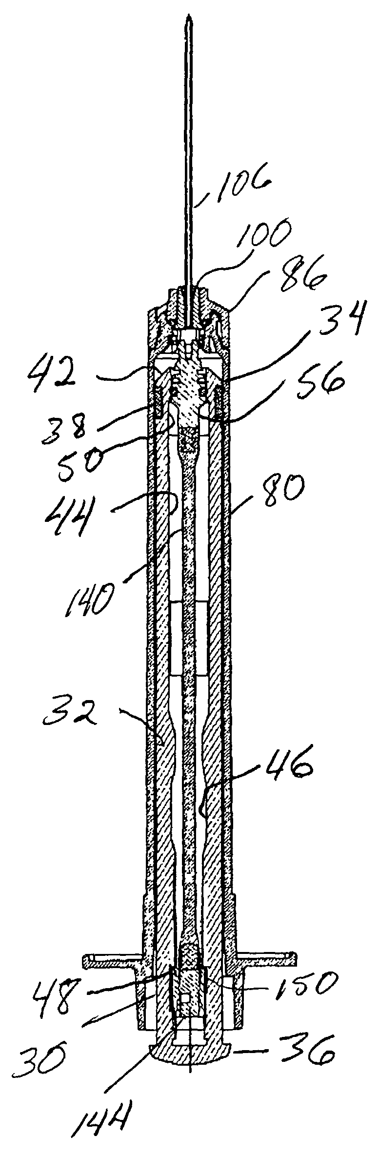
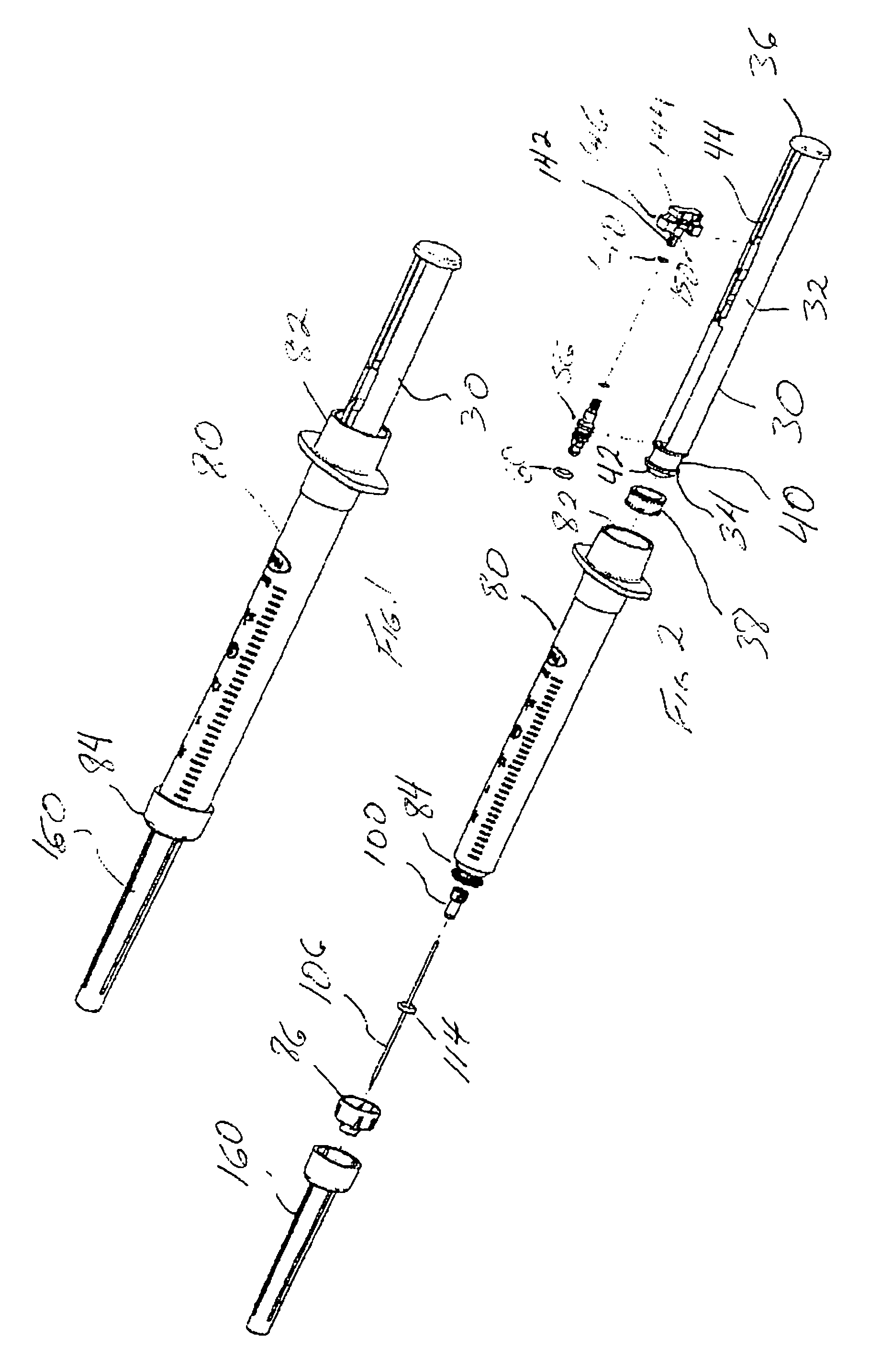
[0034]Turning in detail to the drawings, FIG. 1 illustrates a syringe with a retractable needle. This view illustrates the device as shipped. FIG. 2 illustrates the same device in an exploded assembly view as including a barrel 80, a plunger assembly 30, a protective needle cap 160 and a needle hub 100 with an associated needle 106.

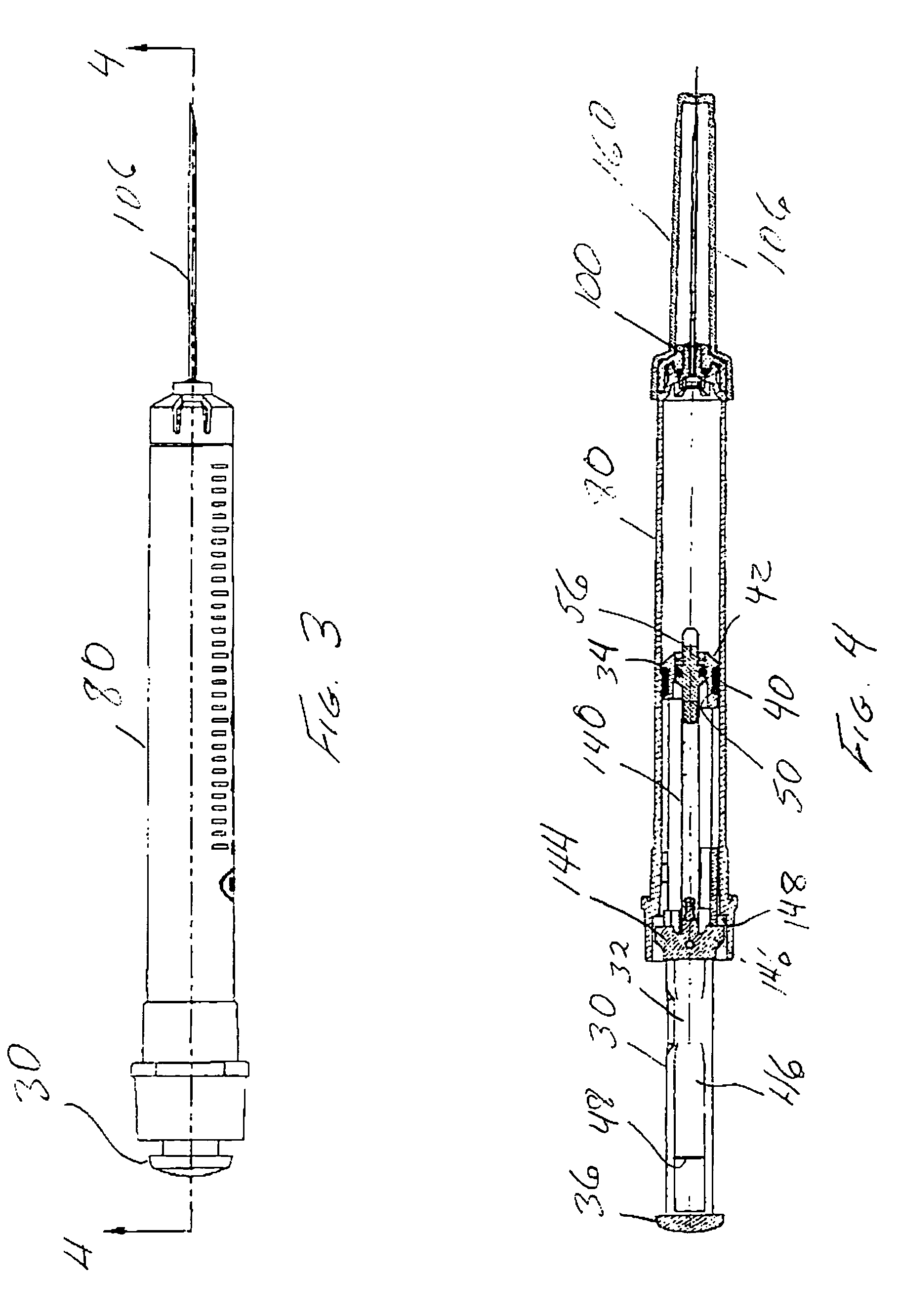
[0035]The plunger assembly is illustrated in various positions within the barrel 80 in FIGS. 4, 5, 6 and 7. Further, the plunger assembly is shown by itself in FIG. 11. The plunger assembly 30 includes a molded body 32 having a seal end 34 and an outer end 36. The outer end 36 defines a thumb button for actuation of the syringe while the seal end 34 acts as a piston with a ring seal 38 extending about a waist 40. A substantially conical forward surface defines a driver surface 42 which will be described later as interacting with the forward end of the barrel.

[0036]A cavity 44 lies between the seal end 34 and the outer end 36. This cavity is shown to be op...


PUM


Abstract

A hypodermic syringe employing a plunger slidably disposed within a barrel. The plunger has a mounting hole extending through the seal end thereof to receive a mandrel. The mandrel has a flexible flange to be releasably engaged with the plunger. A spring element withdraws the mandrel into a cavity within the plunger upon full extension of the plunger within the barrel. The barrel includes a hub retainer at the forward end thereof and a needle hub retained therein the mandrel includes barbed tines with surfaces having axes of the conical surfaces that are displaced from one another such that movement of the tines toward one another also brings the axes closer. A catch associated with the back end of the spring element coupled with the mandrel at the other end cooperates with shoulders on smooth surfaces within the cavities to retain tension within the bungee. The hub retainer and the needle hub cooperate to insure that the needle hub is constrained to limited motion such that the mandrel will fully engage the needle hub.

Description

BACKGROUND OF THE INVENTION[0001]The field of the present invention is syringes and, more particularly, syringes offering protection against accidental sharps injury.[0002]Accidental sharps injuries, in this context needle sticks, have long been recognized as potentially dangerous to health care workers. More recently, the transmission of serious and potentially fatal infections from such sharps injuries have created greater concern. Legislation has been contemplated in a number of States and before the Occupation Safety and Health Administration which would require safe needle technology.[0003]A number of approaches have been undertaken to provide protection against such sharps injuries. International Publication WO 01 / 41843A1 discloses a syringe with a retractable needle which includes a plunger having a cavity extending longitudinally therein. A spring element is located in the cavity and is fixed to a mandrel extending into the syringe barrel from the mandrel which attaches to a...

Claims


Application Information

Patent Timeline
Patent Type & Authority Patents(United States)
IPC IPC(8): A61M5/00A61M5/32A61M5/50
CPCA61M5/3234A61M5/508A61M2005/3235A61M2005/3241A61M5/00A61M5/178A61M5/32A61M5/315
Inventor MONTALVO, RUDYFEITH, RAYMOND P.MCCONNELL-MONTALVO, SUSANMARANO-FORD, APRIL
Owner HYPOGUARD USA
Why Eureka
Try Eureka