
Velocity responsive power control

a power control and velocity technology, applied in the field of wireless communication devices, can solve the problems of inability to optimally control power levels at all velocity ranges, inability to maximize power levels, and excessive transmission of signals by base stations receiving fixed-rate power control commands, so as to facilitate efficient use of available transmit power and maximize the number of communications devices

Inactive Publication Date: 2009-02-17
QUALCOMM INC
View PDF14 Cites 2 Cited by
  • Summary
  • Abstract
  • Description
  • Claims
  • Application Information

AI Technical Summary

Benefits of technology

[0013]The present invention advantageously facilitates an efficient use of available transmit power and maximizes the number of communications devices that a base station can support.

Problems solved by technology

Unfortunately, for these fixed command rate systems, as the rate of amplitude and phase fluctuations varies, the effectiveness of these commands also varies.
Therefore, conventional systems that employ the transmission of power control commands at a fixed rate are unable to optimally control power levels at all velocity ranges.
As a consequence, base stations receiving fixed-rate power control commands transmit signals having excessive power that could otherwise be used to support additional communications devices.
Accordingly, system capacity becomes wasted.

Method used


Image

  • Velocity responsive power control
  • Velocity responsive power control
  • Velocity responsive power control

Examples


Embodiment Construction

I. Communications Environment

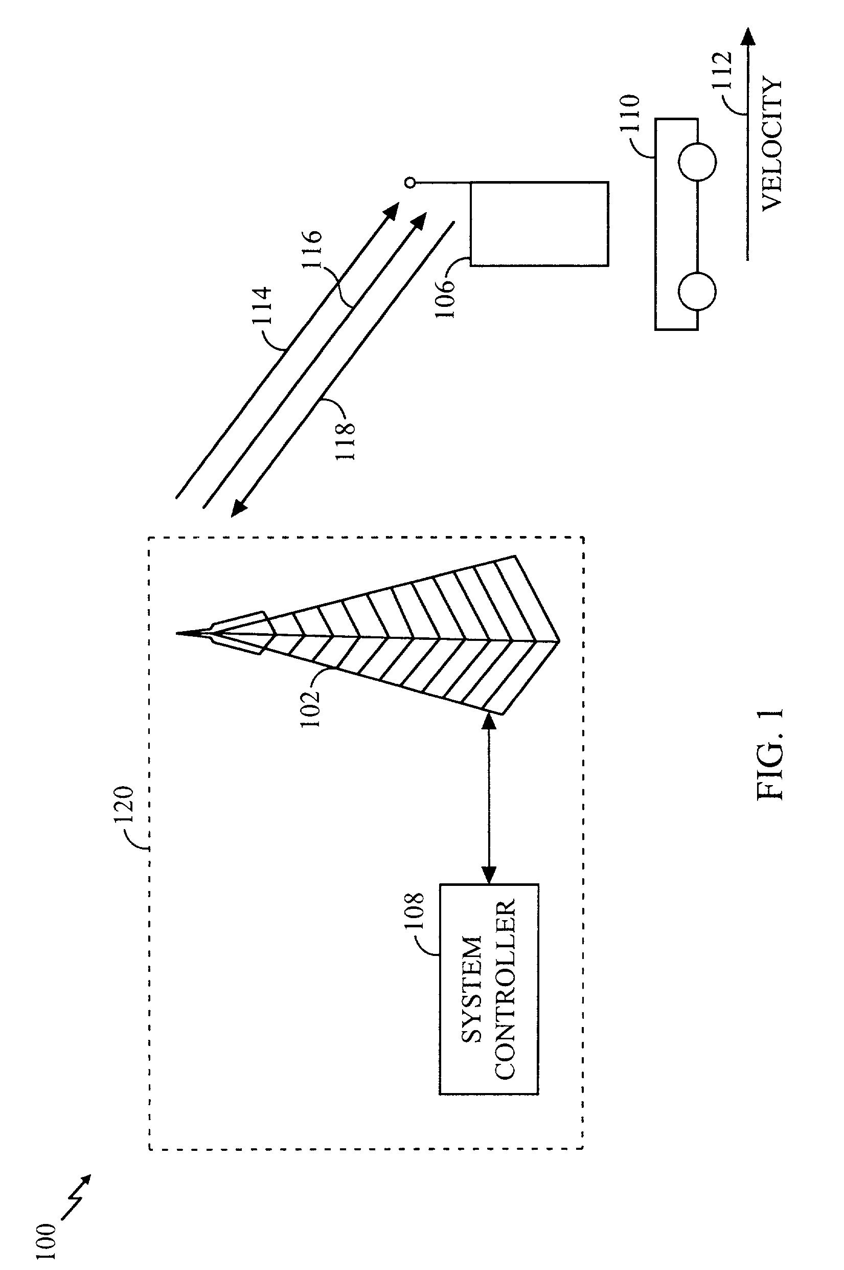
[0026]Before describing the invention in detail, it is helpful to describe an example environment in which the invention may be implemented. The present invention is particularly useful in mobile communications environments. FIG. 1 illustrates such an environment.

[0027]FIG. 1 is a block diagram of an exemplary mobile communications environment 100. Communications environment 100 includes a base station 102, a system controller 108, a wireless communications device (WCD) 106, and a mobile platform 110.

[0028]Base station 102 is coupled to system controller 108. Together, base station 102 and system controller 108 are part of a wireless communications system (WCS) 120 that exchanges information with WCD 106. This information exchange provides services, such as cellular telephony, and personal communications system (PCS) applications.

[0029]This exchange of information between WCS 120 and WCD 106 occurs across various communications channels. Of these various...


PUM


Abstract

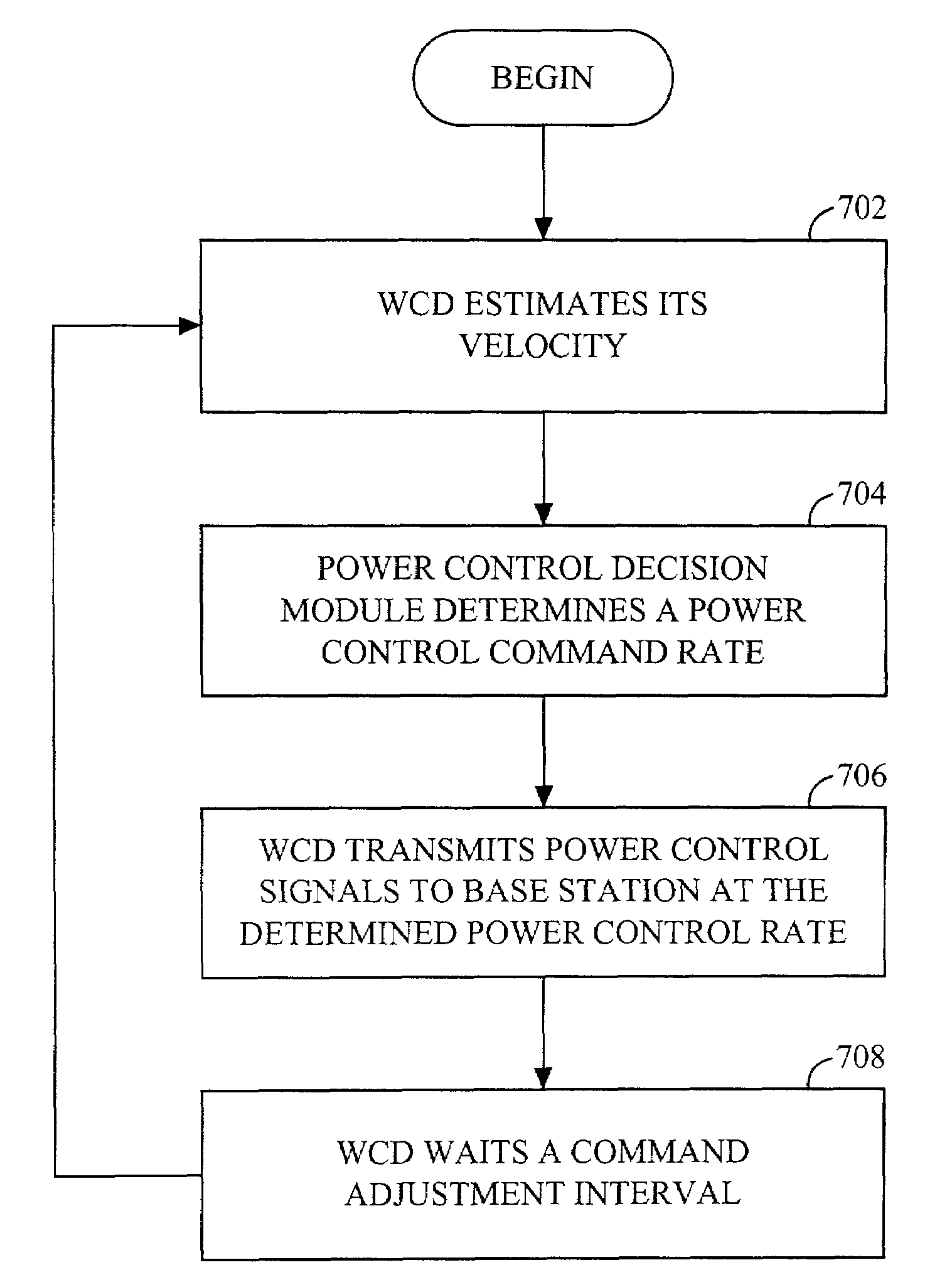
The velocity of a wireless communications device (WCD) (106) is estimated. In response to this estimate a power control command rate is determined. The WCD 106 transmits power control signals to a base station (102) according to the power control command rate. The power control command rate may be determined by mapping the estimated velocity to a velocity range, and selecting a rate that corresponds to the velocity range as the power control command rate. Velocity is estimated by measuring a level crossing rate of a multipath signal.

Description

BACKGROUND OF THE INVENTION[0001]1. Field of the Invention[0002]The present invention relates generally to wireless communications devices. More specifically, the present invention relates to power control algorithms for use in mobile communications environments.[0003]2. Related Art[0004]Mobile communications devices, such as wireless phones, are often employed in vehicles or other mobile platforms that travel at relatively high velocities. For example, mobile communications devices are often used in automobiles, trains, and airplanes that travel at speeds as fast as several hundred kilometers per hour.[0005]In wireless communications environments, signals are often transmitted between a transmitter and a receiver across a fading channel. When the transmitter and the receiver have a relative velocity with respect to each other, signals received from such fading channels exhibit fluctuations in amplitude and phase. These fluctuations have a peak rate that is proportional to this rela...

Claims


Application Information

Patent Timeline
Patent Type & Authority Patents(United States)
IPC IPC(8): H04B7/00H04B1/00H04B7/005H04J13/00H04W52/28H04W52/60
CPCH04W52/282H04W52/60
Inventor SIH, GILBERT CHRISTOPHERPATEL, SHIMMANEKVETCHAVIT, THUNYACHATE
Owner QUALCOMM INC
Learn More