
Method and system for visually representing telephone call tree interface

a call tree and interface technology, applied in the field of telephone communication, can solve the problems of confusing call tree, patient's concern and frustration about the rejection of payment requests, and multiple attempts by callers, and achieve the effect of reducing the number of calls

Inactive Publication Date: 2009-02-17
IBM CORP
View PDF13 Cites 27 Cited by
  • Summary
  • Abstract
  • Description
  • Claims
  • Application Information

AI Technical Summary

Benefits of technology

The present invention provides a way for people to use a visual interface to interact with a telephone call tree. This can be done through wire-line, wireless, data network, or IP phones. The interface shows different options for the caller to select, and they can enter a waiting queue for the option they choose. This makes it easier for callers to navigate through the call tree and make calls.

Problems solved by technology

However, these cost reductions are usually offset by the inconveniences forced on the customers, who typically have to wade through a long, confusing and sometimes frustrating maze of options in menu form.
A significant drawback of existing call tree systems is that they typically require callers to make multiple attempts before they can traverse the menu options successfully.
If the healthcare provider fails to submit the appropriate paperwork to the insurance provider in order to support the alleged services performed, the insurance provider might reject the patient's submission.
If the insurance provider's answering system uses a complicated and / or confusing call tree, having to navigate such a complicated or confusing call tree only exacerbates the patient's concern and frustration about the rejected payment request.
Another drawback of existing call tree systems is that significantly different call trees are typically used in similar technologies.

Method used


Image

  • Method and system for visually representing telephone call tree interface
  • Method and system for visually representing telephone call tree interface
  • Method and system for visually representing telephone call tree interface

Examples


Embodiment Construction

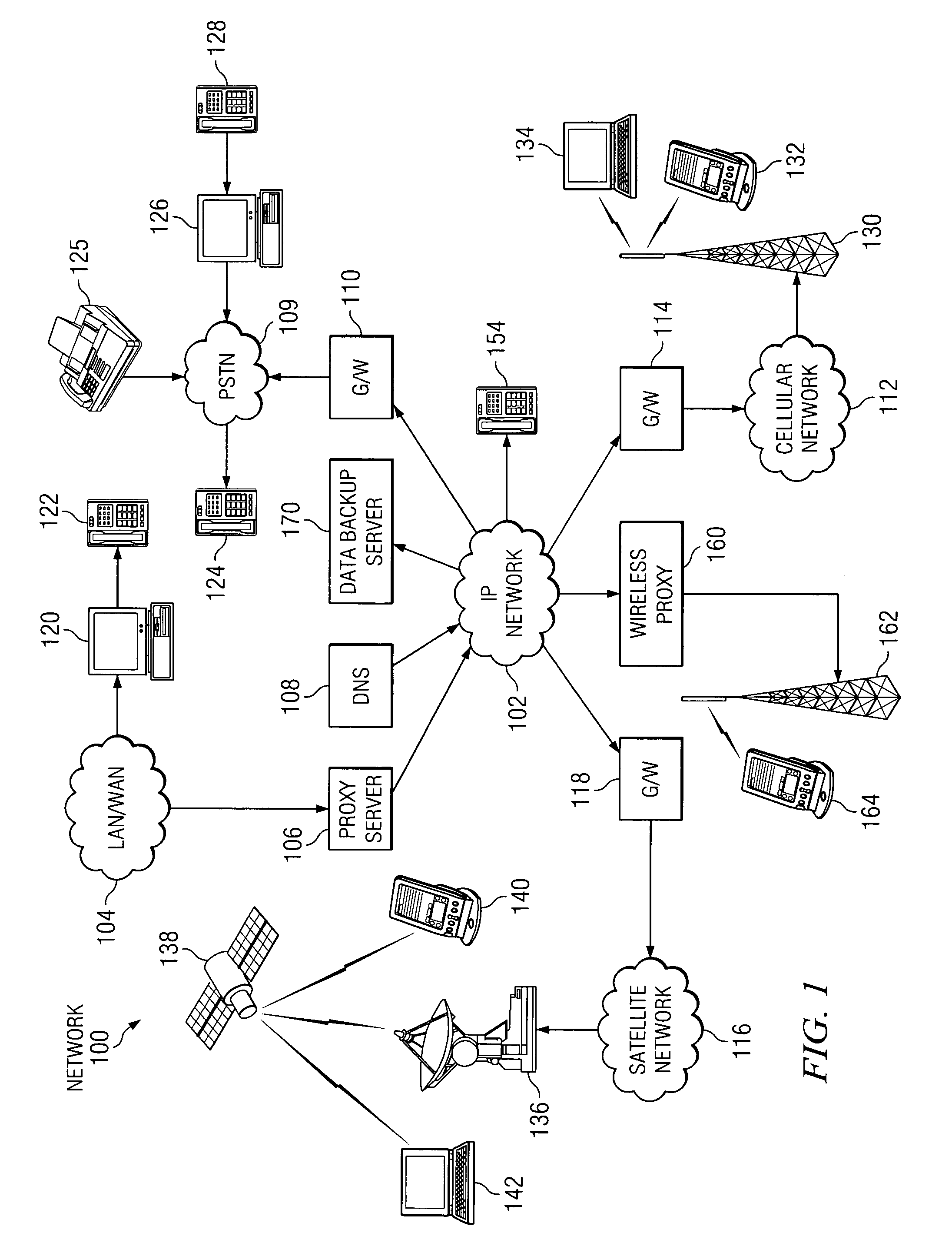
[0015]With reference now to the figures, and in particular with reference to FIG. 1, a system diagram illustrating a plurality of interconnected, heterogeneous networks in which the present invention may be implemented is depicted. As illustrated, exemplary system 100 includes IP network 102, Local Area Network (LAN) / Wide Area Network (WAN) 104, Public Switched Telephone Network (PSTN) 109, cellular wireless network 112, and satellite communications network 116. As such, system 100 makes up a plurality of heterogeneous networks, and one or more of these networks can be used to implement the present invention.

[0016]IP network 102 can be a publicly available IP network, a private IP network, or a combination of public and private IP networks. In any case, IP network 102 operates according to the Internet Protocol and can route packets through its numerous switches and transmission paths. IP networks are generally known in the art to be expandable, fairly easy to use and heavily suppor...


PUM


Abstract

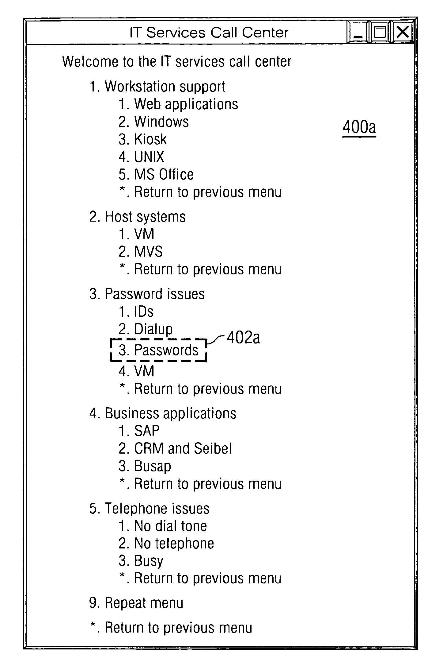
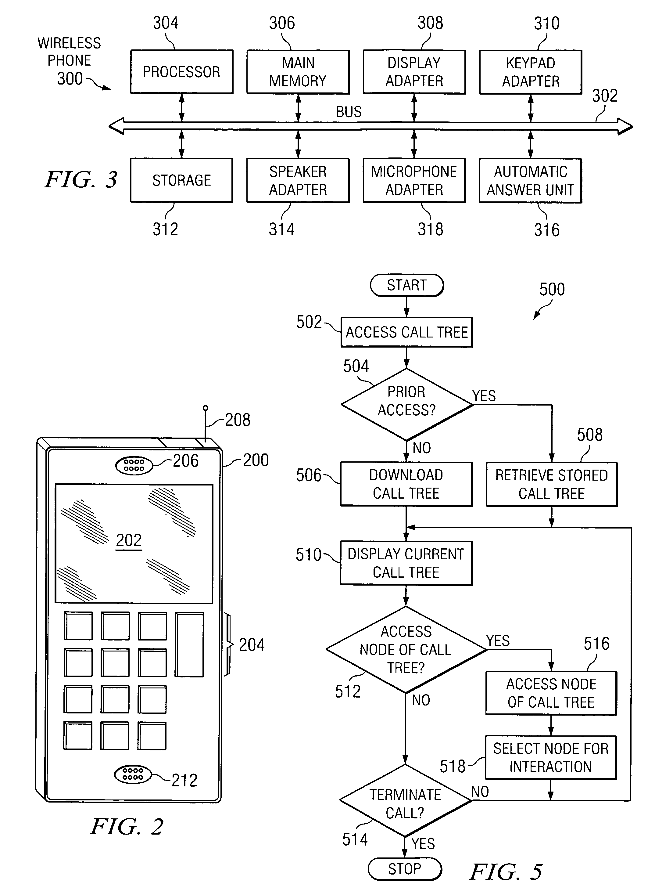
A method, system and computer instructions for visually representing telephone call tree interfaces for interaction by users of data network phones, such as, for example, wire-line telephones, data network telephones, or IP telephones. A caller can connect to an automated telephone answering service, and view a display of an interactive, visual interface for a call tree. The display can depict actions that can be taken with respect to nodes of the call tree. The visual interface can show details about one or more nodes of the call tree, and the caller can select a node for interaction and enter a wait queue associated with the selected node. For example, the caller can use a wire-line telephone, wireless telephone, data network telephone, or IP telephone to interact with, navigate and / or modify the displayed call tree.

Description

BACKGROUND OF THE INVENTION[0001]1. Technical Field[0002]The present invention relates generally to telephony, and in particular, but not exclusively, to a method and system for visually representing call tree interfaces for interaction by users of telephones such as, for example, wire-line telephones, wireless telephones, data network telephones, or Internet Protocol (IP) telephones.[0003]2. Description of Related Art[0004]Automated telephone answering systems are typically software applications that answer and process incoming telephone calls. So-called “call path” or “call tree” systems are automated telephone answering systems uzsed by businesses to reduce the costs of answering customers' calls. However, these cost reductions are usually offset by the inconveniences forced on the customers, who typically have to wade through a long, confusing and sometimes frustrating maze of options in menu form. These menus of options are commonly referred to as “call trees”.[0005]A significa...

Claims


Application Information

Patent Timeline
Patent Type & Authority Patents(United States)
IPC IPC(8): H04M3/42H04L12/66H04M5/00H04M3/00H04M3/493
CPCH04M3/4938H04M2201/38H04M2201/42
Inventor KUMHYR, DAVID BRUCE
Owner IBM CORP
Learn More