
Adjustable spinal prosthesis

a spinal prosthesis and adjustable technology, applied in the field of spinal prosthesis accessories and methods, can solve the problems of unsatisfactory anatomy, damaged articular processes, or facets of one or more vertebrae, and unable to articulate or properly align vertebrae with each other,

Active Publication Date: 2009-02-17
PREMIA SPINE +1
View PDF18 Cites 25 Cited by
  • Summary
  • Abstract
  • Description
  • Claims
  • Application Information

AI Technical Summary

Benefits of technology

The present invention provides a spinal prosthesis that can be adjusted in-situ to a desired lordotic angle. The prosthesis includes two movable spinal components that are attached to the spinal structures using a fastening device. The fastening device can be tightened to secure the spinal components at a desired orientation. The spinal components can also pivot with respect to each other and the fastening device to accommodate non-straight surfaces. The flexure assembly allows for movement of the spinal components relative to each other, and the elastomeric boot provides flexibility in all directions. The technical effects of the invention include improved spinal stability and flexibility, as well as the ability to adjust the spinal prosthesis to the patient's needs.

Problems solved by technology

Through disease or injury, the laminae, spinous process, articular processes, or facets of one or more vertebral bodies can become damaged, such that the vertebrae no longer articulate or properly align with each other.
This can result in an undesired anatomy, loss of mobility, and pain or discomfort.
One problem addressed by the prior art is that of the spinal lordosis.
A problem that needs to be addressed in spinal prosthetic devices is that of matching or correcting the lordotic angle.
However, the “adjustment” that Reilley et al. provides is nothing more than a prosthesis pre-manufactured and customized to a particular lordotic angle.

Method used


Image

  • Adjustable spinal prosthesis
  • Adjustable spinal prosthesis
  • Adjustable spinal prosthesis

Examples


Embodiment Construction

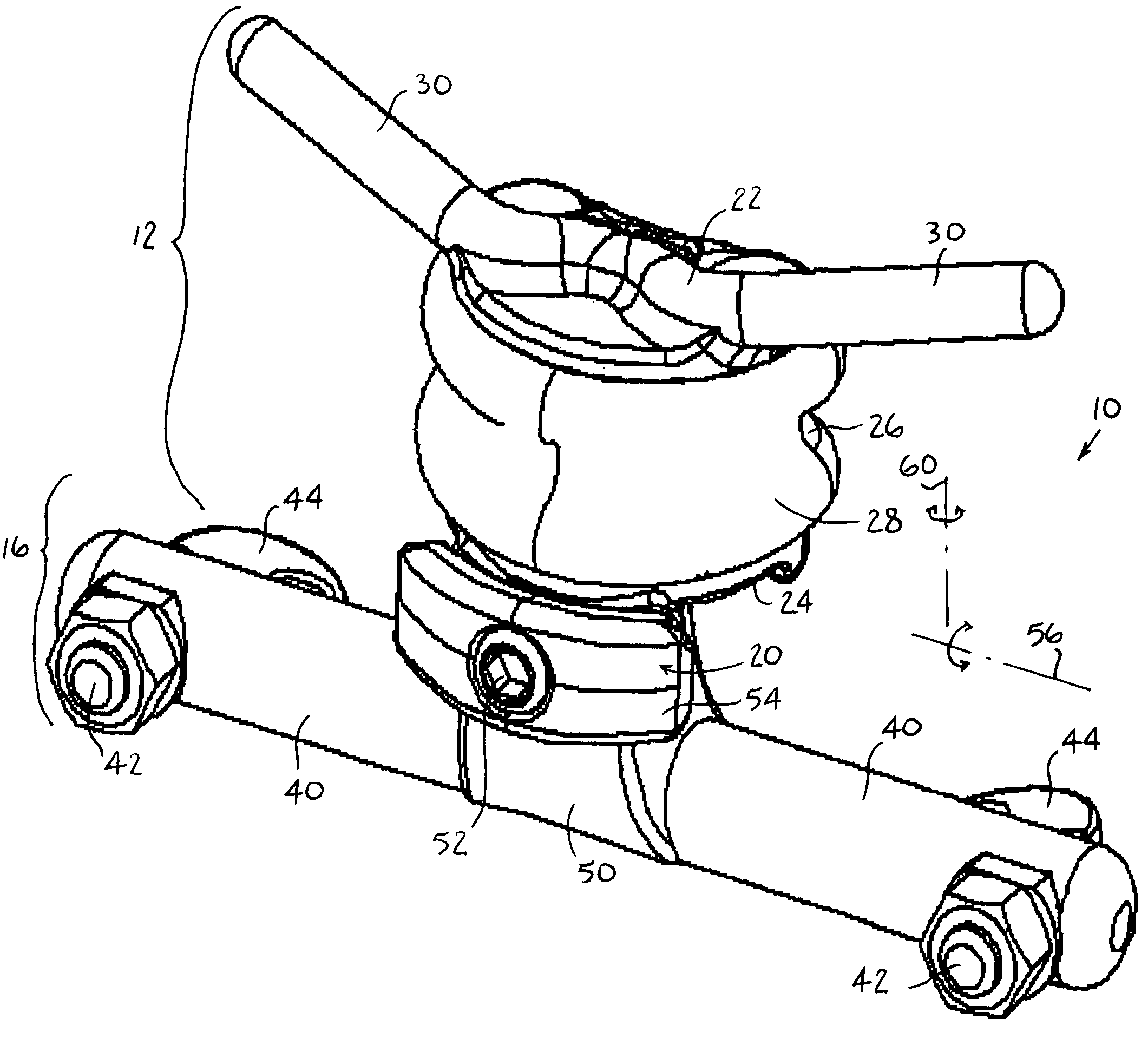
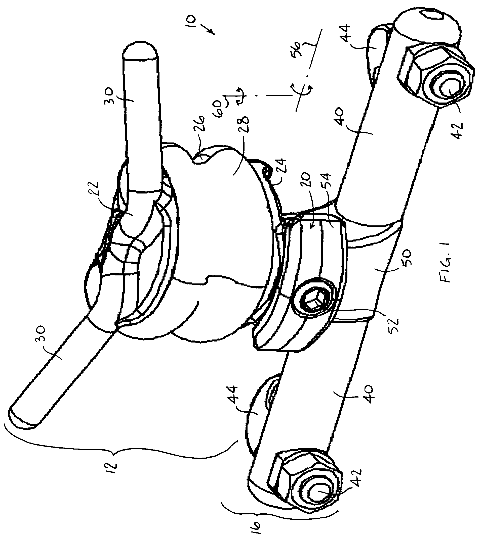
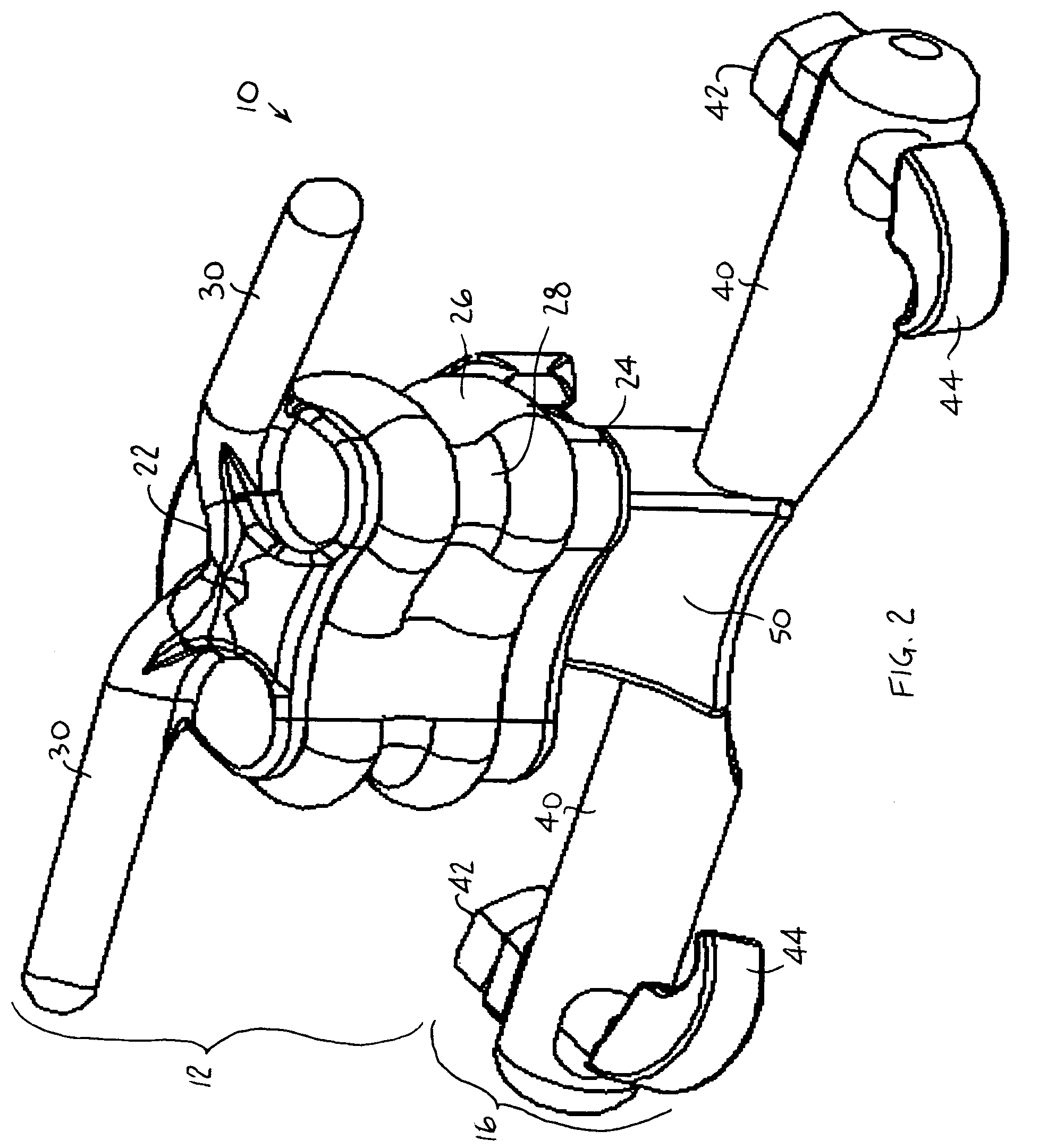
[0017]Reference is now made to FIGS. 1-4, which illustrate a spinal prosthesis 10, constructed and operative in accordance with an embodiment of the present invention.

[0018]The spinal prosthesis 10 may include a first spinal prosthetic member 12, which may be attached to a first spinal structure 14, such as but not limited to, a vertebra (e.g., L3, as seen in FIG. 4). The spinal prosthesis 10 may also include a second spinal prosthetic member 16, which may be attached to a second spinal structure 18, such as but not limited to, a vertebra (e.g., L4, as seen in FIG. 4). One non-limiting way of attaching the first and second spinal prosthetic member 12 and 16 to the first and second spinal structures 14 and 18 is described more in detail hereinbelow.

[0019]The first and second spinal prosthetic members 12 and 16 may be movably attached to one another with a fastening device 20. As will be described more in detail hereinbelow, the fastening device 20 has a non-tightened position which p...


PUM


Abstract

Apparatus including a first spinal prosthetic member attachable to a first spinal structure, and a second spinal prosthetic member attachable to a second spinal structure, the first and second spinal prosthetic members being movably attached to one another with a fastening device, the fastening device having a non-tightened position which permits spatial movement of the first and second spinal prosthetic members with respect to one another at a desired orientation, and a tightened position which fixes the first and second spinal prosthetic members at the desired orientation.

Description

FIELD OF THE INVENTION[0001]The present invention is generally related to apparatus and methods for spinal prostheses.BACKGROUND OF THE INVENTION[0002]Through disease or injury, the laminae, spinous process, articular processes, or facets of one or more vertebral bodies can become damaged, such that the vertebrae no longer articulate or properly align with each other. This can result in an undesired anatomy, loss of mobility, and pain or discomfort. For example, spinal stenosis, as well as spondylosis, spondylolisthesis, osteoarthritis and other degenerative phenomena may cause back pain, especially lower back pain, such as in the lumbosacral (L4-S1) region. Such phenomena may be caused by a narrowing of the spinal canal by a variety of causes that result in the pinching of the spinal cord and / or nerves in the spine.[0003]The prior art has many spinal prostheses designed to help the patient with various back problems. One problem addressed by the prior art is that of the spinal lord...

Claims


Application Information

Patent Timeline
Patent Type & Authority Patents(United States)
IPC IPC(8): A61F2/44
CPCA61B17/7043A61F2/44
Inventor ARNIN, URISUDIN, YURIFLEISCHER, SHAI
Owner PREMIA SPINE
Learn More