
Filter element for embolic protection device

a filter element and protection device technology, applied in the direction of dilators, catheters, ultrafiltration, etc., to achieve the effect of facilitating the retrieval of captured embolic material

Inactive Publication Date: 2009-02-17
SALVIAC
View PDF577 Cites 74 Cited by
  • Summary
  • Abstract
  • Description
  • Claims
  • Application Information

AI Technical Summary

Benefits of technology

[0004]A practical problem that arises with filter elements of such embolic protection devices is that they should be able to accommodate blood vessels of different diameter as it would be impractical to manufacture a large range of filters each of different size to accommodate all possible diameters of blood vessel. To provide flexibility and accommodate a range of vessel sizes with a given size of filter a relatively soft and elastic filter body material can be used. It is, however, important that the filter when deployed maintains its shape during use and to prevent distortion or collapsing of the filter body in use. Because of this and also the need for adequate strength in the body material, the walls of the filter body tend to be relatively thick. This presents a problem in that the filter then has a relatively large crossing profile when in the collapsed deployment position, which is undesirable.
[0010]the filter body being at least partially of laminate construction comprising a membrane coated with a coating which is biocompatible, the thickness of the coating being from 4% to 40% of the thickness of the membrane to enhance the mechanical characteristics of the filter body.

Problems solved by technology

A practical problem that arises with filter elements of such embolic protection devices is that they should be able to accommodate blood vessels of different diameter as it would be impractical to manufacture a large range of filters each of different size to accommodate all possible diameters of blood vessel.
This presents a problem in that the filter then has a relatively large crossing profile when in the collapsed deployment position, which is undesirable.

Method used


Image

  • Filter element for embolic protection device
  • Filter element for embolic protection device
  • Filter element for embolic protection device

Examples


Embodiment Construction

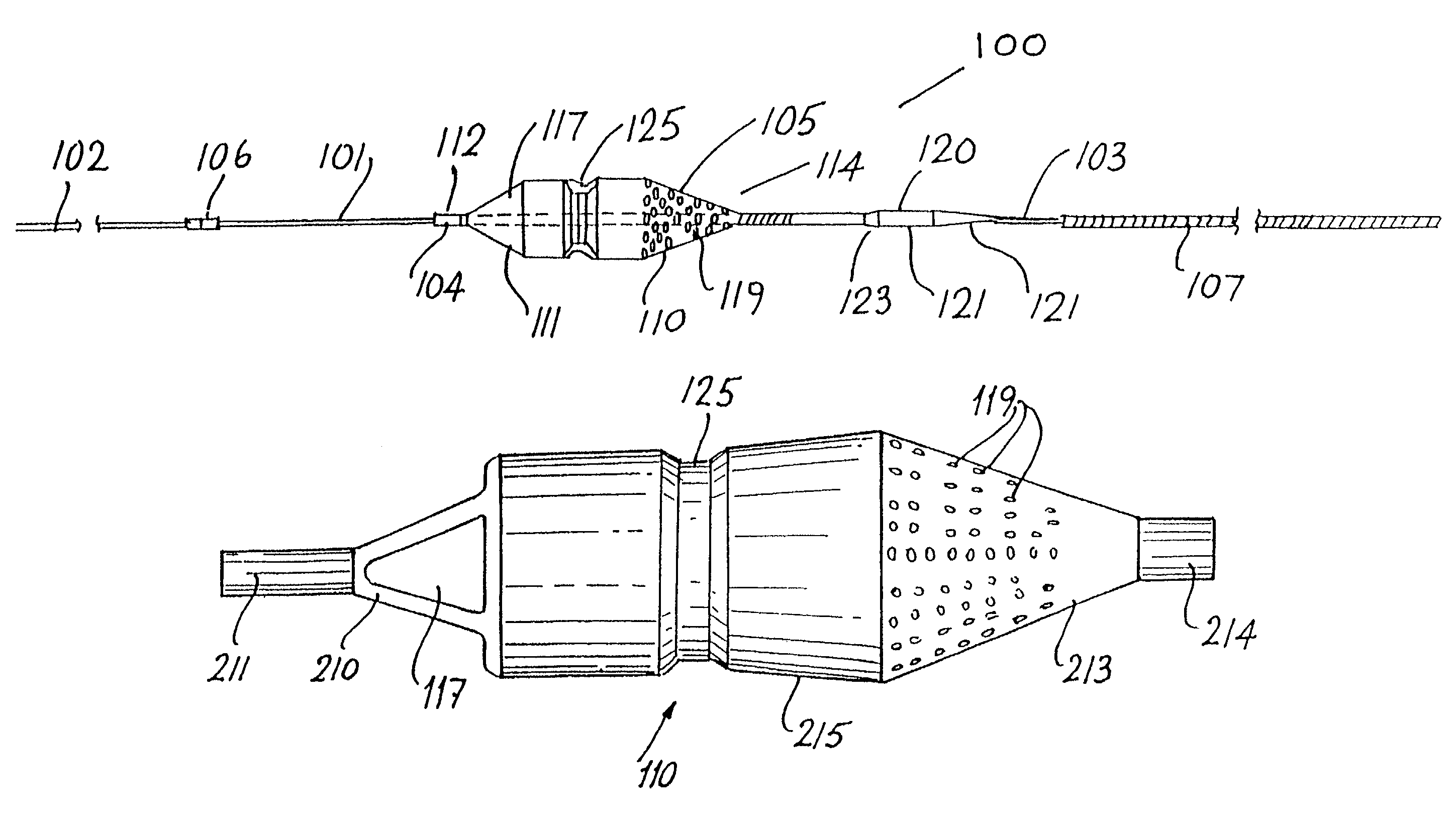
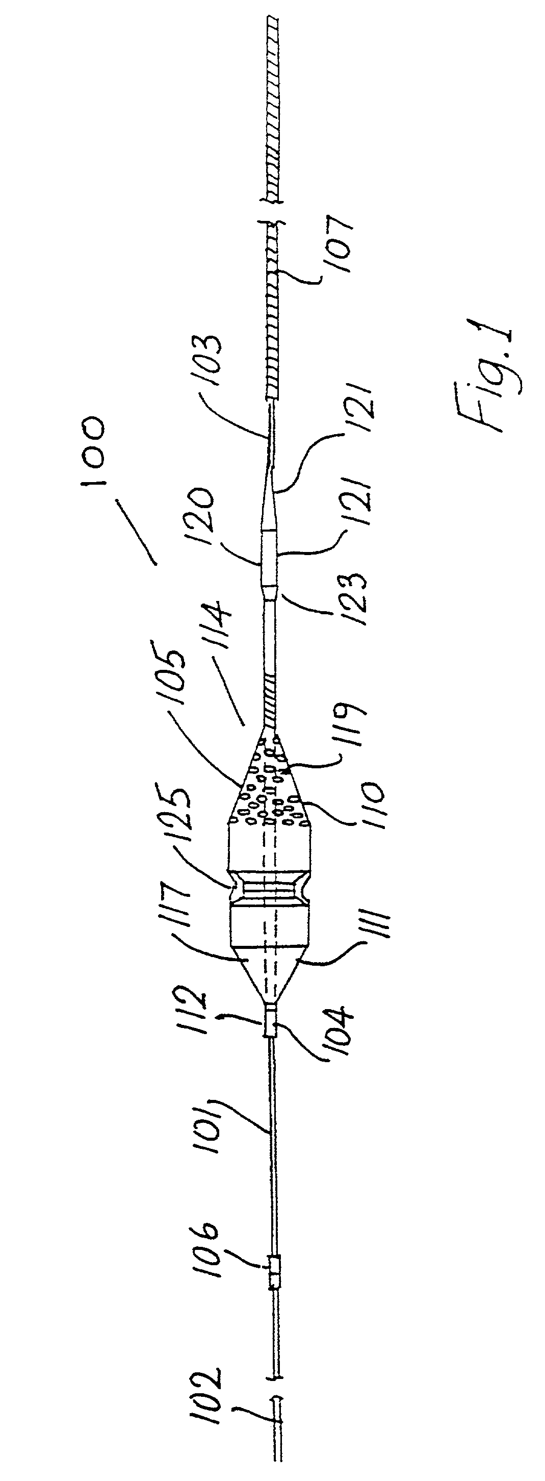
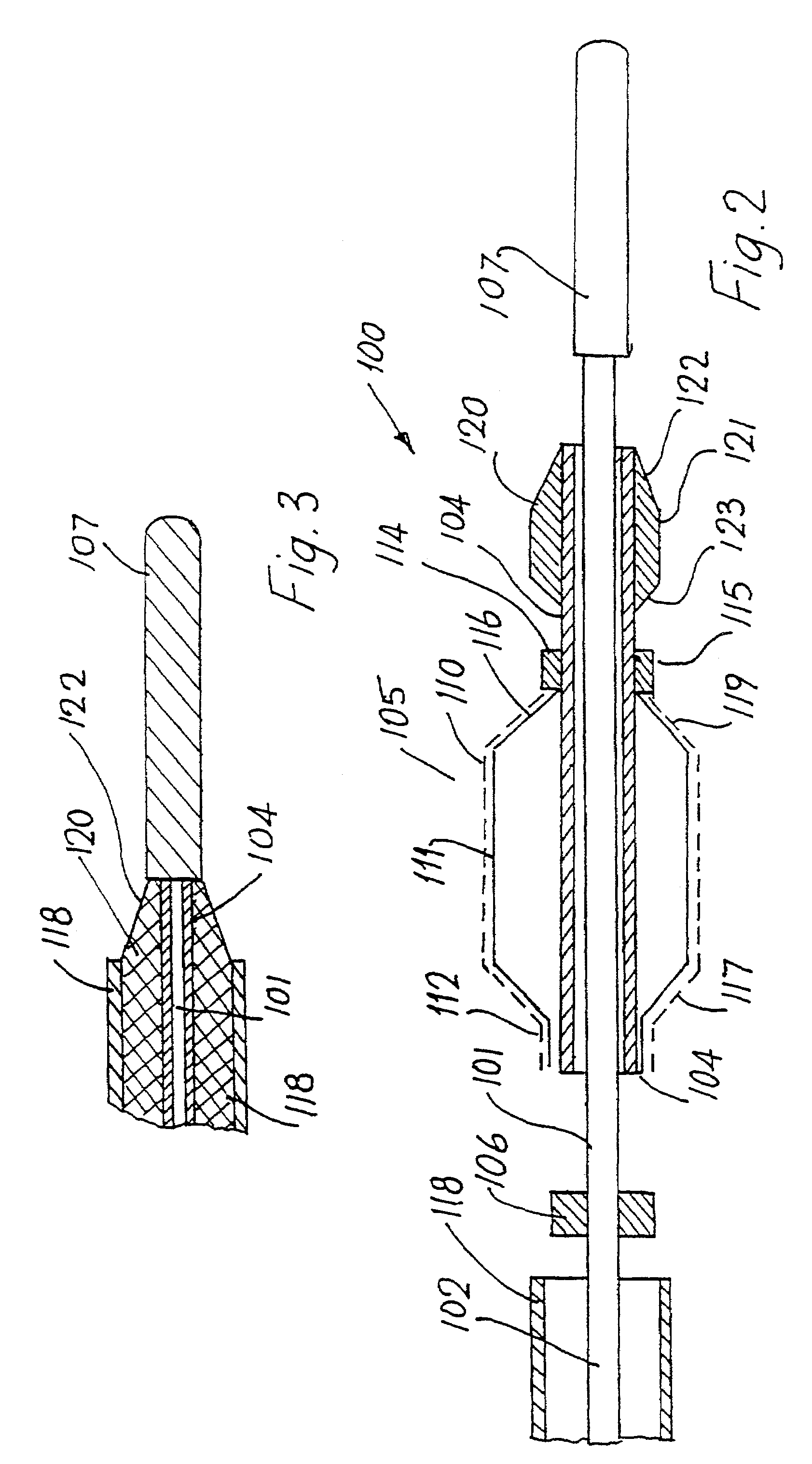
[0078]Referring to FIGS. 1 to 13 there is illustrated an embolic protection device as described in our WO-A-9923976 indicated generally by the reference number 100. The device100 has a guidewire 101 with a proximal end 102 and a distal end 103. A tubular sleeve 104 is slidably mounted on the guidewire 101. A collapsible filter 105 is mounted on the sleeve 104, the filter 105 being movable between a collapsed stored position against the sleeve 104 and an expanded position as shown in the drawings extended outwardly of the sleeve 104 for deployment in a blood vessel.

[0079]The sleeve 104 is slidable on the guidewire 101 between a pair of spaced-apart end stops, namely an inner stop 106 and an outer stop which in this case is formed by a spring tip 107 at the distal end 103 of the guidewire 101.

[0080]The filter 105 comprises a filter body 110 mounted over a collapsible support frame 111. The filter body 110 is mounted to the sleeve 104 at each end, the body 110 being rigidly attached to...


PUM

PropertyMeasurementUnit
diameteraaaaaaaaaa
diameteraaaaaaaaaa
sizesaaaaaaaaaa

Abstract

A collapsible filter element for a transcatheter embolic protection device comprises a collapsible filter body which is movable between a collapsed stored position for movement through a vascular system and an expanded position for extension across a blood vessel such that blood passing through the blood vessel is delivered through the filter element. A proximal inlet portion of the filter body has one or more inlet openings sized to allow blood and embolic material enter the filter body and a distal outlet portion of the filter body has a plurality of outlet openings sized to allow through-passage of blood, but to retain embolic material within the filter body. The filter body is at least partially of laminate construction comprising a membrane coated with a coating which is biocompatible, the thickness of the coating being from 4% to 40% of the thickness of the membrane. The coating may be of hydrophilic material. To facilitate retrieval of captured embolic material the distal portion and / or an intermediate portion of the filter membrane may be stretchable. The filter body may have regions of varying hardness or stiffness.

Description

CROSS REFERENCE TO RELATED APPLICATIONS[0001]This application is a continuation of international application number PCT / IE00 / 00053, filed May 8, 2000, the content of which is incorporated herein by reference, and claims the priority of PCT International Application No. PCT / IE99 / 00036, filed May 7, 1999, and PCT International Application No. PCT / IE99 / 00033, filed May 7, 1999.[0002]This invention relates to a filter element for a transcatheter embolic protection device.INTRODUCTION[0003]The invention is particularly concerned with filter elements for transcatheter embolic protection devices of the type described in our WO-A-9923976. One type of such embolic filter essentially comprises a filter body mounted on an associated collapsible support frame which can be collapsed against the guide wire by means of a catheter for deployment of the filter through a patient's vascular system. Upon retraction of the catheter the support frame and filter body expand outwardly from the guidewire ac...

Claims


Application Information

Patent Timeline
Patent Type & Authority Patents(United States)
IPC IPC(8): A61M29/00A61B17/22A61B17/00A61F2/01A61M1/34A61M25/00B01D61/14B01D63/00B01D71/26B01D71/46B01D71/54B01D71/56
CPCA61F2/013A61F2002/015A61F2002/018A61F2250/0018A61F2250/0036A61F2250/0067A61F2230/0006A61F2230/0067A61F2/0108
Inventor VALE, DAVIDBRADY, EAMON
Owner SALVIAC
Learn More