Ultrasonic diagnosing system
a diagnostic system and ultrasonic technology, applied in the field of ultrasonic diagnostic equipment, can solve the problems of difficult to clarify the scanning part of the luminal portion, the first problem is not solved in real-time during the examination, and the spread of the lesion along the luminal portion
- Summary
- Abstract
- Description
- Claims
- Application Information
AI Technical Summary
Benefits of technology
Problems solved by technology
Method used
Image
Examples
first embodiment
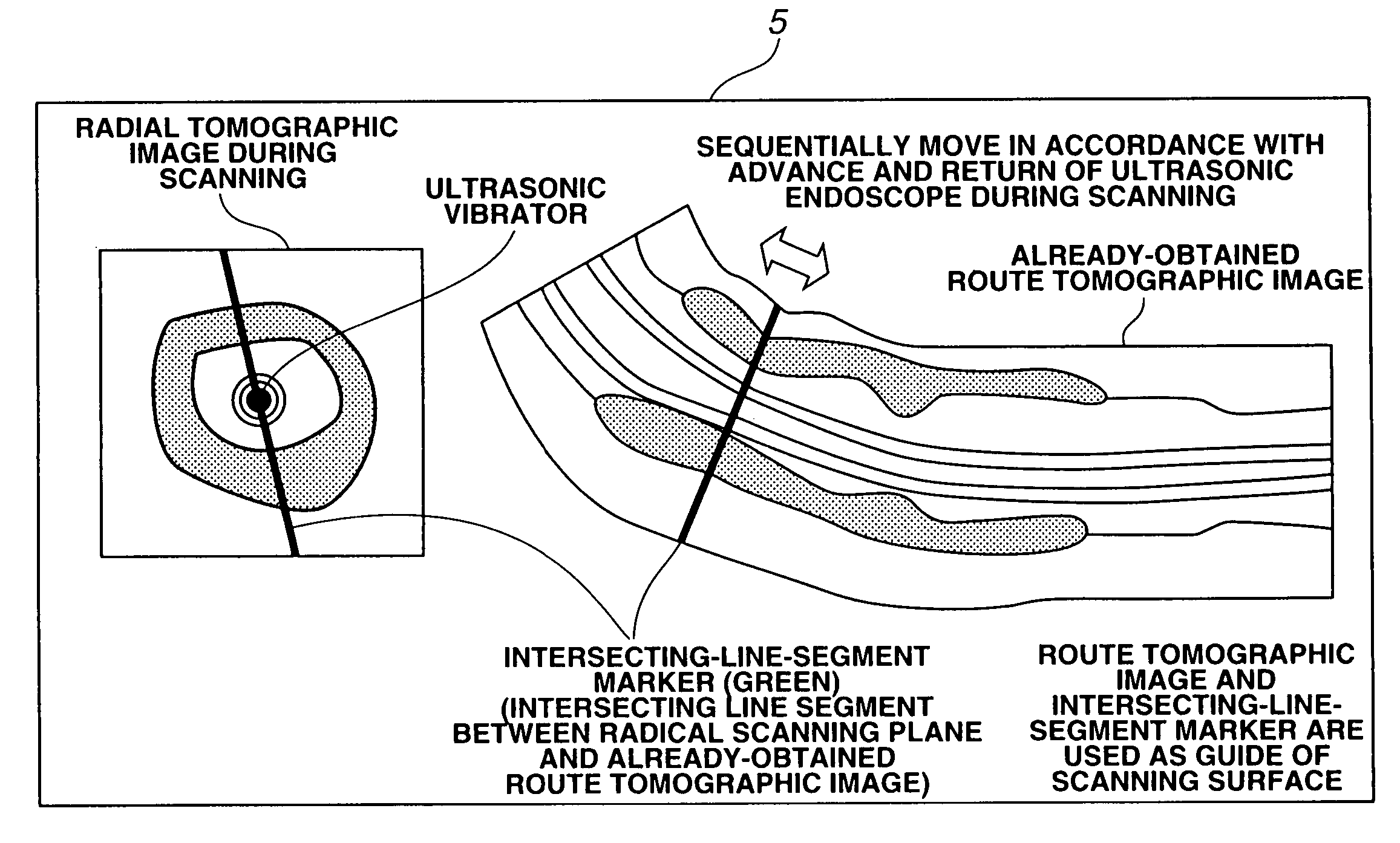
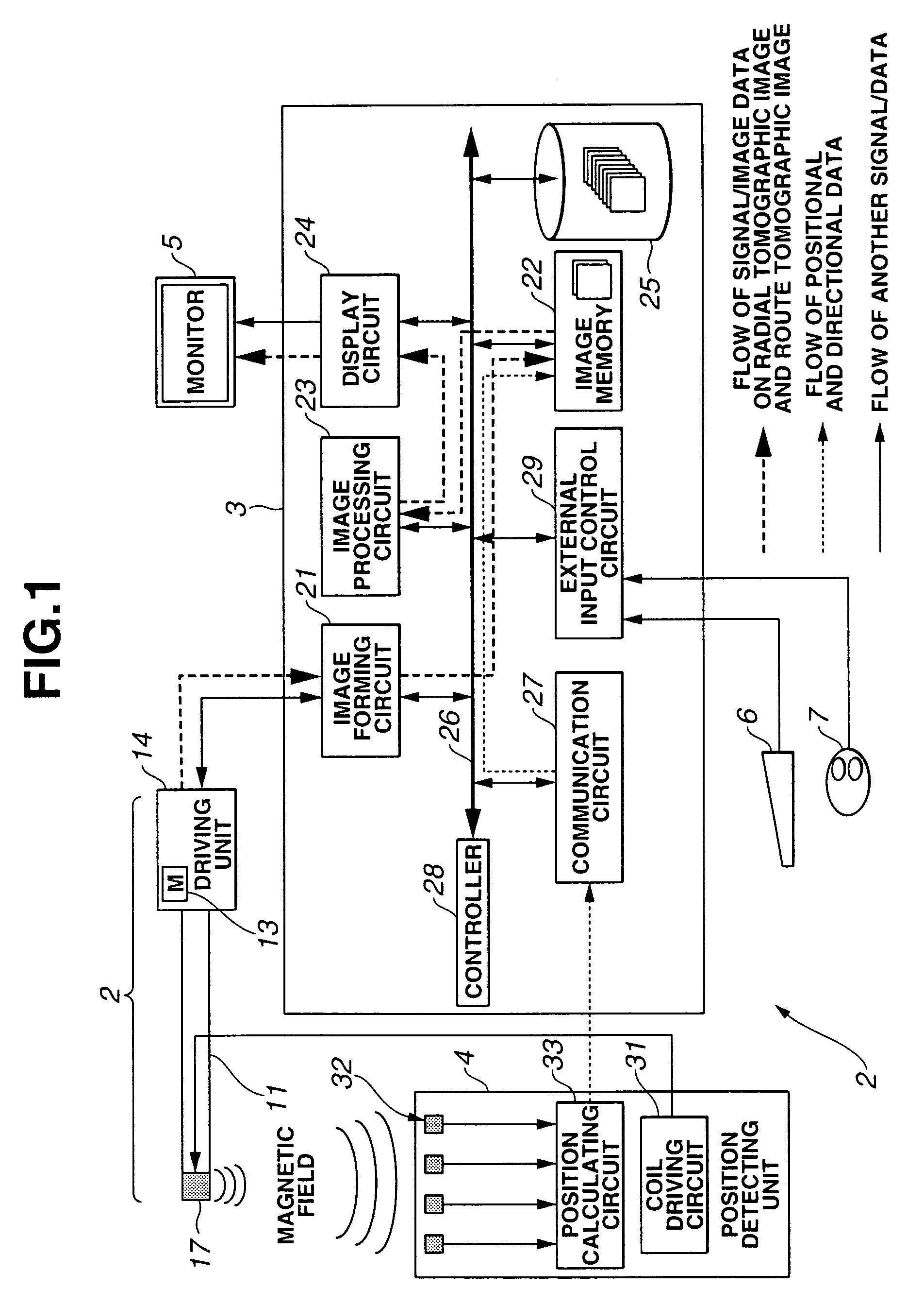
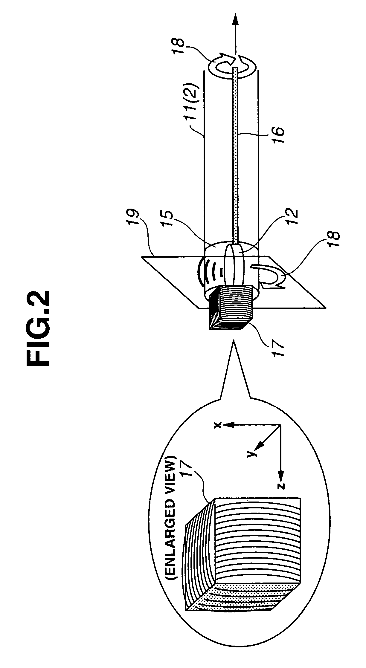
[0034]Hereinbelow, a description is given of the structure and the operation of an ultrasonic diagnostic apparatus according to the first embodiment with reference to FIGS. 1 to 10.
[0035](Structure)
[0036]Referring to FIG. 1, an ultrasonic diagnostic apparatus 1 according to the first embodiment comprises an ultrasonic endoscope 2, an ultrasonic observing portion 3, a position detecting unit 4, a monitor 5, a keyboard 6, and a mouse 7.
[0037]The ultrasonic endoscope 2 has an inserting portion 11 which is inserted in the body cavity of a subject, containing a flexible material, and a driving unit 14 having a motor 13 for driving an ultrasonic vibrator (which will be described later) of the inserting portion edge.
[0038]The state of the edge of the inserting portion 11 will be described with reference to FIG. 2. Referring to FIG. 2, the inserting portion 11 has, at the edge thereof, an acoustic transparent edge cap 15 which is made of a material for transmitting ultrasonic waves. The edg...
second embodiment
[0120]The second embodiment is almost the same as the first embodiment, therefore, only different points are described, the same reference numerals denote the same components, and a description thereof is omitted.
[0121]Hereinbelow, a description is given of the structure and the operation of the ultrasonic diagnostic apparatus according to the second embodiment with reference to FIGS. 11 and 12.
[0122](Structure)
[0123]Referring to FIG. 11, the driving unit 14 according to the second embodiment does not have the motor. However, referring to FIG. 12, the ultrasonic vibrator is cut in rectangles at the edge of the inserting portion in an ultrasonic endoscope 2a according to the second embodiment and thus a circular array (hereinafter, referred to as an ultrasonic vibrator array) 51 is aligned around the inserting axis. Ultrasonic vibrators forming the ultrasonic vibrator array 51 are connected to the image forming circuit 21 in the ultrasonic observing unit 3 via the signal lines and th...
third embodiment
[0135]The third embodiment is substantially the same as the first embodiment, therefore, only different points are described, the same reference numerals denotes the same components, and a description thereof is omitted.
[0136](Structure and Operation)
[0137]Hereinbelow, the structure and the operation of an ultrasonic diagnostic apparatus will be described according to the third embodiment with reference to FIG. 13. The entire structural diagram is the same as FIG. 11.
[0138]Referring to FIG. 13, a radial scanning ultrasonic probe according to the third embodiment uses a capsule ultrasonic endoscope (hereinafter, referred to as the capsule ultrasonic endoscope) 101 as the radial scanning ultrasonic probe.
[0139]The capsule ultrasonic endoscope 101 comprises the transmitting coil 17, the ultrasonic vibrator 12, a rigid shaft 104, an ultracompact motor 102, and a signal cable 103. Unlike the first embodiment, the driving unit 14 does not have the motor 13. In place of the motor 13 in the...
PUM
 Abstract
Description
Claims
Application Information
 - R&D
- Intellectual Property
- Life Sciences
- Materials
- Tech Scout
- Unparalleled Data Quality
- Higher Quality Content
- 60% Fewer Hallucinations
Browse by: Latest US Patents, China's latest patents, Technical Efficacy Thesaurus, Application Domain, Technology Topic, Popular Technical Reports.
© 2025 PatSnap. All rights reserved.Legal|Privacy policy|Modern Slavery Act Transparency Statement|Sitemap|About US| Contact US: help@patsnap.com


