
Tractor

a tractor and frame technology, applied in the field of tractor, can solve the problems of increasing the number of parts, wasting time and effort in assembling operation, and increasing the manufacturing cos

Active Publication Date: 2009-01-13
YANMAR POWER TECHNOLOGY CO LTD
View PDF7 Cites 30 Cited by
  • Summary
  • Abstract
  • Description
  • Claims
  • Application Information

AI Technical Summary

Benefits of technology

The present invention provides a tractor with a hood that is easier to assemble and reduces manufacturing costs. The hood is made up of a fixed-side forming body and an open-and-close side forming body. The fixed-side forming body is split into a left half and a right half, which are connected to a connecting support body on the front of the body frame using a connecting body. The front-end abutting portions of the half forming members are guided inwardly and clamped together using a connecting bolt and a fastening nut. This design reduces the number of parts, simplifies assembly, and reduces manufacturing costs.

Problems solved by technology

However, in the above-mentioned hood, the fixed-side forming body is split into three parts consisting of the front grille forming member and the pair of left and right side panel forming members and hence, there exists a drawback that the number of the parts is increased so that a manufacturing cost is pushed up and, at the same time, these parts must be individually fixed to the body frame and hence, an assembling operation takes time and efforts.

Method used


Image

  • Tractor
  • Tractor
  • Tractor

Examples


Embodiment Construction

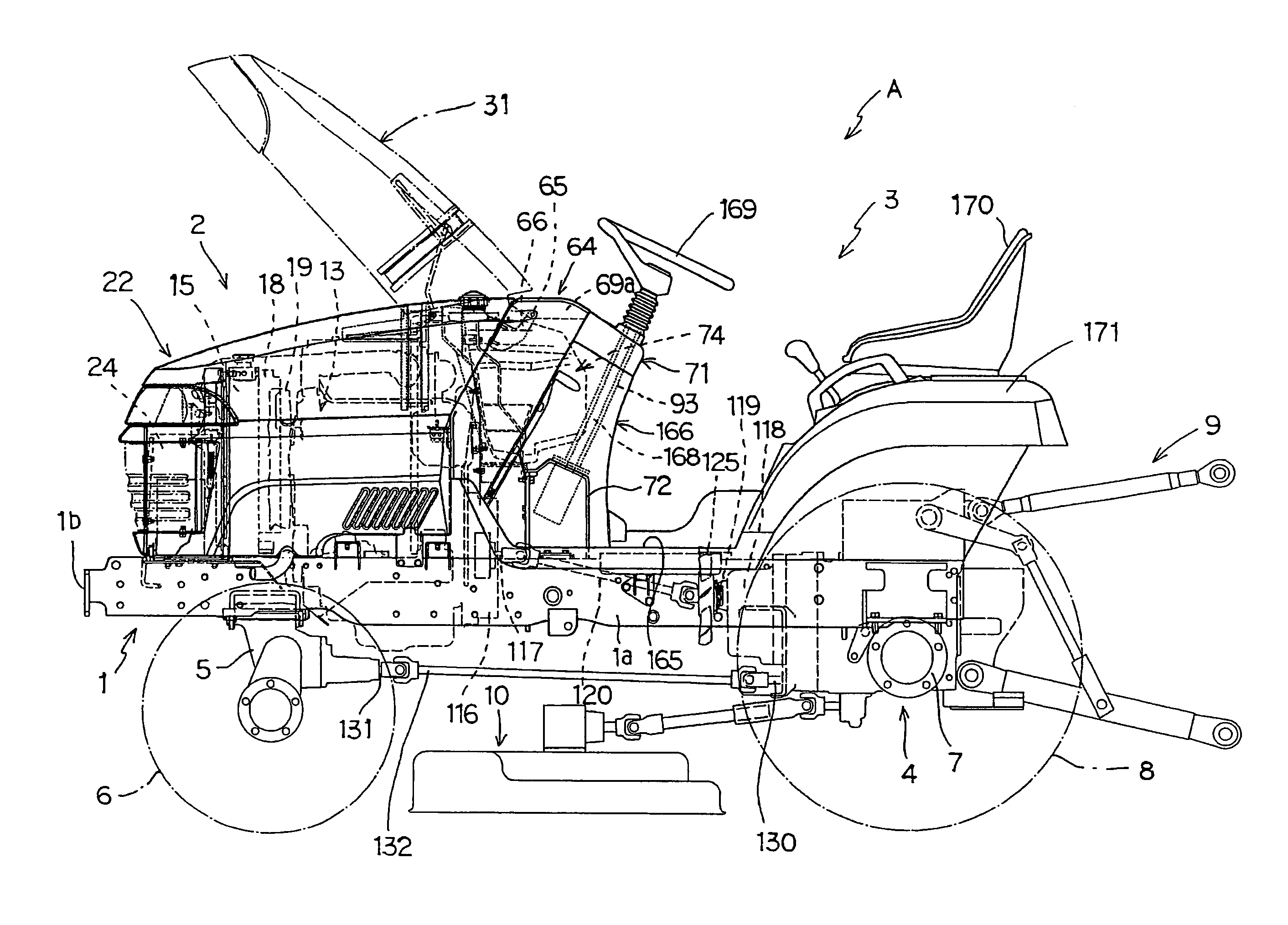
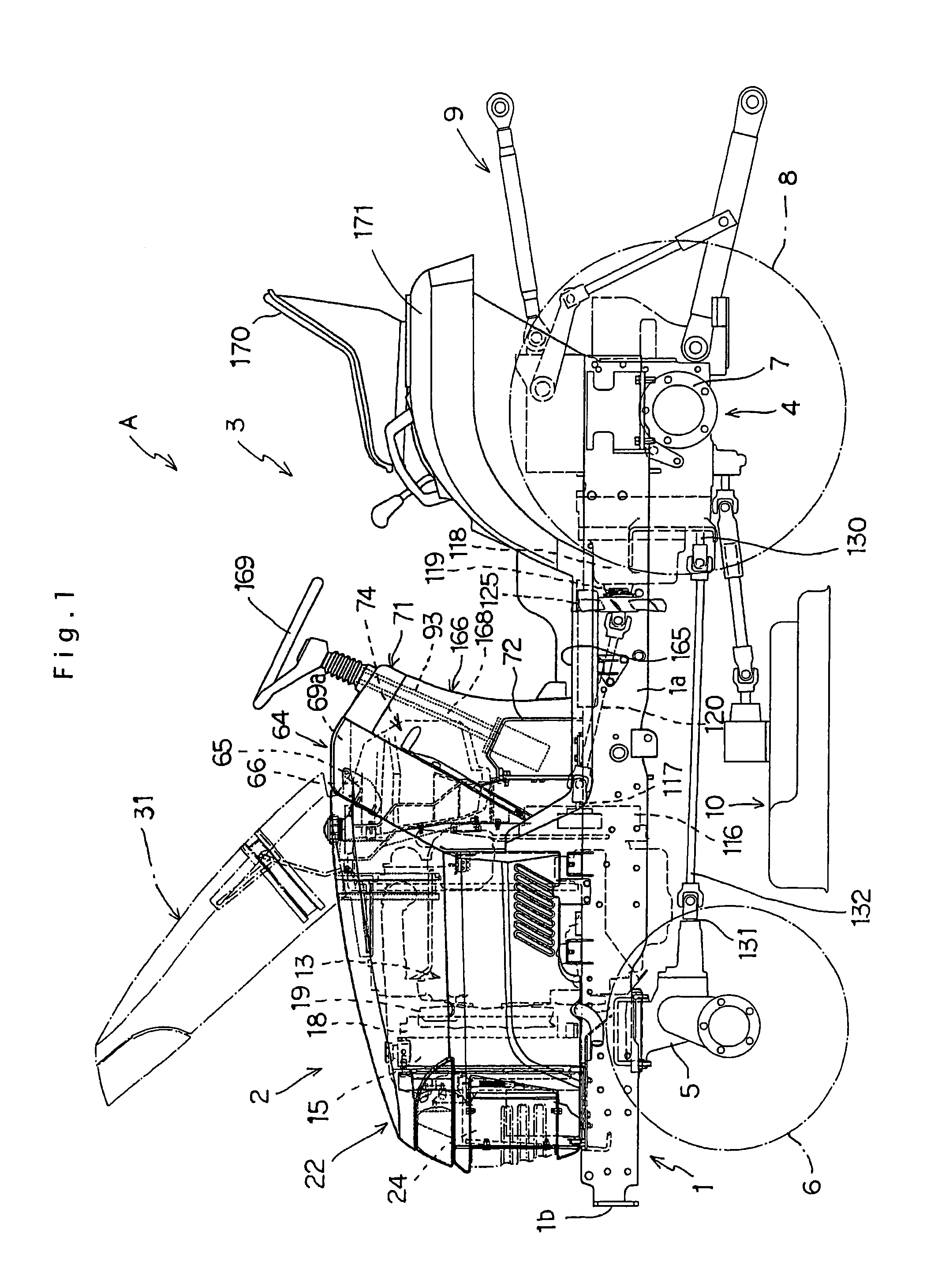
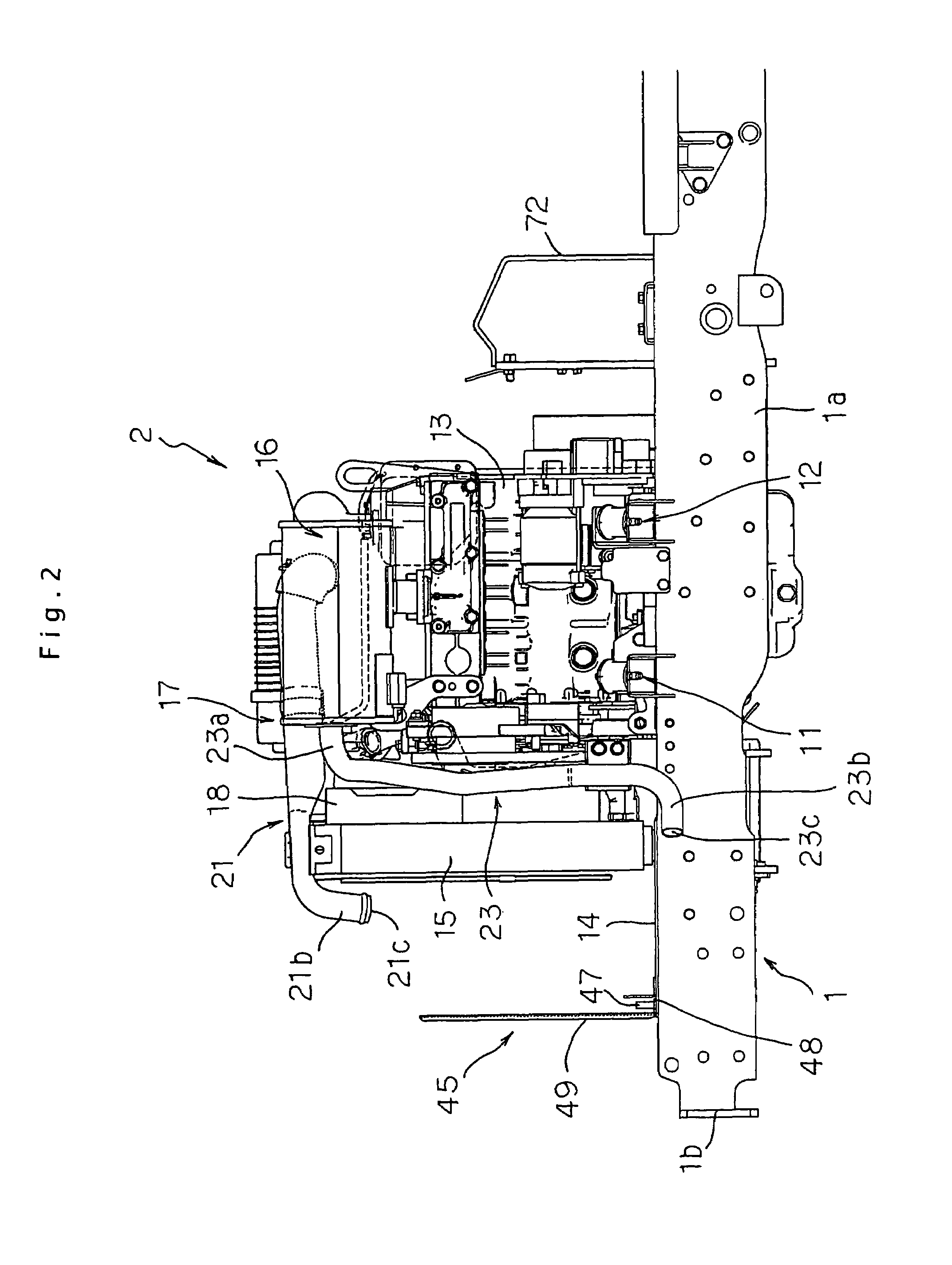
[0029]Symbol A shown in FIG. 1 indicates a tractor according to the present invention. The tractor A is configured as follows. Above the a body frame 1, a prime mover part 2 is arranged on a front portion of the body frame 1 and a driving portion 3 is arranged on a rear portion of the body frame 1, a transmission part 4 is arranged below a driver's seat 170 of the driving portion 3. Below the body frame 1, a pair of left and right front wheels 6, 6 are mounted on the front portion of the body frame 1 by way of a front axle case 5 and, at the same time, a pair of left and right rear wheels 8, 8 are mounted on the transmission part 4 by way of a rear axle case 7. Numeral 9 indicates an elevation link mechanism and numeral 10 indicates a mower.

[0030]The body frame 1 is, as shown in FIG. 1 to FIG. 5, formed of a pair of left and right longitudinally extending members 1a, 1a which extend in the longitudinal direction and a lateral extending member 1b which extends between front ends of b...


PUM


Abstract

A tractor realizes the remarkable reduction of time and efforts necessary for an assembling operation of a hood. Here, a hood is split into a fixed-side forming body which is fixed to the body frame and an open-and-close side forming body which can open / close an upper surface of the fixed-side forming body, and the fixed-side forming body is split into a left half forming member and a right half forming member. On the other hand, a connecting support body is formed on the front portion of the body frame in an upwardly raised state and, front-end abutting portions of left-and-right-side half forming members are connected and fixed to the connecting support body using a connecting body in a state that the front-end abutting portions are sandwiched between the connecting support body and the connecting body in the longitudinal direction.

Description

TECHNICAL FIELD[0001]The present invention relates to a tractor.BACKGROUND ART[0002]Conventionally, as one mode of a tractor, there has been known a tractor, wherein a hood which covers a prime mover part is split into a fixed-side forming body which is fixed to a body frame and an open-and-close side forming body which can open / close an upper surface of the fixed-side forming body and, the fixed-side forming body is split into a front grill forming member and a pair of left and right side panel forming members, the front grill forming member and the side panel forming members are connected and fixed to a support frame which is vertically mounted on the body frame. (see Japanese Patent Laid-Open Hei11(1999)-105740, for example)DISCLOSURE OF THE INVENTION[0003]However, in the above-mentioned hood, the fixed-side forming body is split into three parts consisting of the front grille forming member and the pair of left and right side panel forming members and hence, there exists a drawb...

Claims


Application Information

Patent Timeline
Patent Type & Authority Patents(United States)
IPC IPC(8): B60J7/00B62D25/10
CPCB62D25/10
Inventor TOKUHARA, TAKAYUKI
Owner YANMAR POWER TECHNOLOGY CO LTD
Learn More