
On-vehicle radar device and vehicle control system

a technology of vehicle control system and radar device, which is applied in the direction of pedestrian/occupant safety arrangement, navigation instruments, instruments, etc., can solve the problems of inconvenient use of above system, increased cost, and inability of compact vehicle drivers to recognize the state ahead of the large preceding

Active Publication Date: 2009-01-06
DENSO CORP
View PDF6 Cites 12 Cited by
  • Summary
  • Abstract
  • Description
  • Claims
  • Application Information

AI Technical Summary

Benefits of technology

The present invention provides an on-vehicle radar device that can acquire information from a target vehicle's blind spot without needing an infrastructure on the road side. The device includes a transmitting and receiving means, an object sensing means, a target vehicle extracting means, and a blind spot object extracting means. The device can extract a target vehicle and a blind spot object from the sensed objects. The invention also provides a vehicle control system that includes the on-vehicle radar device. The technical effect of the invention is to improve safety and efficiency of vehicle control.

Problems solved by technology

Furthermore, when a preceding vehicle ahead of a compact vehicle is a large vehicle, a view of the driver of the compact vehicle is largely masked by the large preceding vehicle, so that the driver of the compact vehicle cannot recognize a state ahead of the large preceding vehicle.
As a result, for instance, when the driver of the large preceding vehicle suddenly applies the brakes, the drive of the compact vehicle cannot react with it, thereby possibly resulting in the collision.
In the current state where such an infrastructure is not well established, the above system is not useful.
Furthermore, in order to establish the infrastructure at the useful level, the costs are disadvantageously increased.
Also, it is required to provide a communication device to the vehicle side in addition to the road side, resulting in the additional costs to the users.
Therefore, the above technique does not provide the sufficient solution against the blind spot caused by the preceding vehicle.

Method used


Image

  • On-vehicle radar device and vehicle control system
  • On-vehicle radar device and vehicle control system
  • On-vehicle radar device and vehicle control system

Examples


Embodiment Construction

[0025]An embodiment of the present invention will be described with reference to the accompanying drawings.

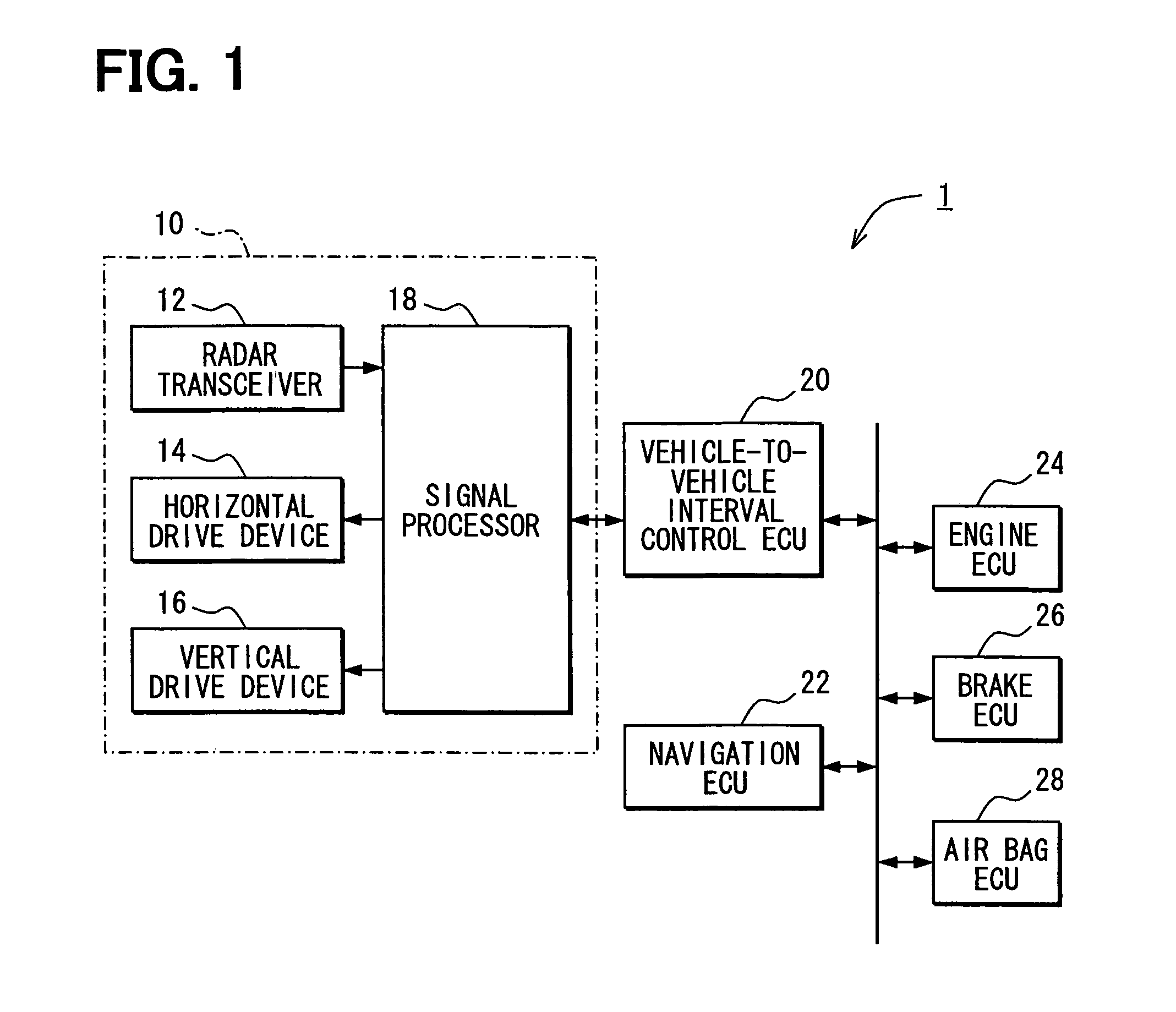
[0026]FIG. 1 is a block diagram showing a structure of a vehicle control system 1 according to the embodiment.

[0027]As shown in FIG. 1, the vehicle control system 1 includes a on-vehicle front radar 10, which is arranged in a front end part of a vehicle. The front radar 10 senses an object(s), such as a preceding vehicle, an obstacle, which is located within a predetermined sensing range ahead of the own vehicle having the vehicle control system 1.

[0028]The front radar 10 is connected to a vehicle-to-vehicle interval control ECU 20, which is in turn connected to a navigation ECU 22, an engine ECU 24, a brake ECU 26 and an air bag ECU 28 through a LAN communication bus. Furthermore, each ECU 20, 22, 24, 26, 28 includes a known microcomputer as its main component. Furthermore, each ECU 20, 22, 24, 26, 28 includes a bus controller to perform communication through the LAN communica...


PUM


Abstract

A radar transceiver of an on-vehicle radar transmits and receives a radar wave. Objects ahead of a vehicle having the on-vehicle radar are sensed based on the reflected radar wave reflected from the objects. A target vehicle to be monitored is extracted from the sensed objects based on the reflected radar wave. Also, a blind spot object, which is present in a blind spot of the target vehicle is extracted from the sensed objects based on the reflected radar wave.

Description

CROSS REFERENCE TO RELATED APPLICATION[0001]This application is based on and incorporates herein by reference Japanese Patent Application No. 2005-175014 filed on Jun. 15, 2005.BACKGROUND OF THE INVENTION[0002]1. Field of the Invention[0003]The present invention relates to an on-vehicle radar device, which is installed on a vehicle and obtains information about objects around the vehicle and also relates to a vehicle control system, which performs a vehicle control operation based on the information obtained by the on-vehicle radar device.[0004]2. Description of Related Art[0005]A traffic accident may occur in the following situations. For instance, a country where drivers keep to the right side of the road, it could happen that when a vehicle approaches an intersection to make a left turn, the driver of that vehicle is surprised with an oncoming straight-through vehicle that has suddenly appeared from a blind spot of an oncoming left turn vehicle, which is about to make a left turn...

Claims


Application Information

Patent Timeline
Patent Type & Authority Patents(United States)
IPC IPC(8): G01S13/00B60R21/00B60T7/12G01C21/00G01C21/26G01S13/931G08G1/16
CPCB60R21/0134B60W10/04B60W10/184B60W30/09B60W30/16B60W40/04G01S13/931G08G1/16B60R2021/01259G01S13/34G01S2013/464G01S2013/9332G01S2013/9325G01S2013/9346G01S2013/935G01S2013/9353G01S2013/9375G08G1/166G08G1/167G01S2013/9319G01S2013/9315G01S2013/93185G01S2013/932G01S2013/93271
Inventor NATSUME, KAZUMA
Owner DENSO CORP
Learn More