
Multi-cyclone apparatus and vacuum cleaner having the same

a multi-cyclone, vacuum cleaner technology, applied in the direction of filtration separation, cleaning filter means, separation processes, etc., can solve the problems of deteriorating contaminant collection efficiency, small-sized contaminants, and relatively large-sized contaminants that can be effectively collected, so as to improve contaminant cleaning efficiency and effectively clean

Inactive Publication Date: 2009-01-06
SAMSUNG GWANGJU ELECTRONICS CO LTD
View PDF11 Cites 52 Cited by
  • Summary
  • Abstract
  • Description
  • Claims
  • Application Information

AI Technical Summary

Benefits of technology

[0009]The present invention has been made to overcome the above-mentioned problems of the art, and therefore, it is an object of the present invention to provide a multi-cyclone apparatus with high contaminant collecting efficiency, which is capable of sequentially separating and collecting contaminants from a drawn air in the order of contaminant particle sizes, and a vacuum cleaner having the same.
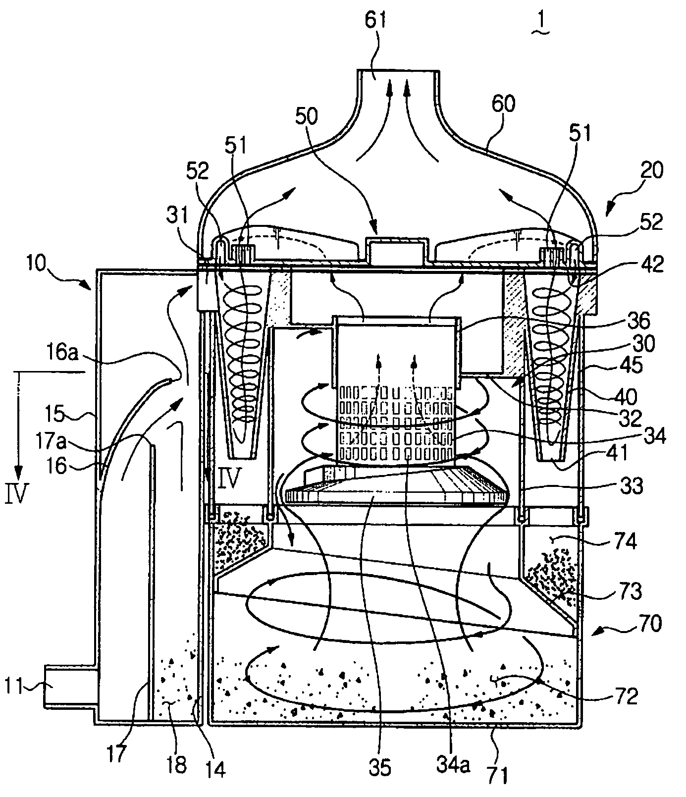
[0017]With a multi-cyclone apparatus and a vacuum cleaner having the same according to the present invention, contaminant-containing air are filtered by three stages, and therefore, contaminant cleaning efficiency improves. More specifically, contaminants can be more effectively cleaned because the large-sized contaminants are separated in the first stage as the air passes through the first collecting unit, the middle-sized contaminants are separated in the second stage as the air passes through the second cyclone, and small-sized contaminants are separated in the third stage as the air passes through the third cyclones.

Problems solved by technology

As such a conventional cyclone apparatus with a single cyclone separates contaminants regardless of sizes of the contaminants, there was a problem that small-sized contaminants such as dust frequently float in the air and discharged through a discharge port, although relatively large-sized contaminants can be effectively collected.
Accordingly, contaminant collecting efficiency deteriorates.

Method used


Image

  • Multi-cyclone apparatus and vacuum cleaner having the same
  • Multi-cyclone apparatus and vacuum cleaner having the same
  • Multi-cyclone apparatus and vacuum cleaner having the same

Examples


Embodiment Construction

[0024]Certain embodiments of the present invention will be described in greater detail with reference to the accompanying drawings.

[0025]In the following description, same drawing reference numerals are used for the same elements even in different drawings. The matters defined in the description such as a detailed construction and elements are nothing but the ones provided to assist in a comprehensive understanding of the invention. Thus, it is apparent that the present invention can be carried out without those defined matters. Also, well-known functions or constructions are not described in detail since they would obscure the invention in unnecessary detail.

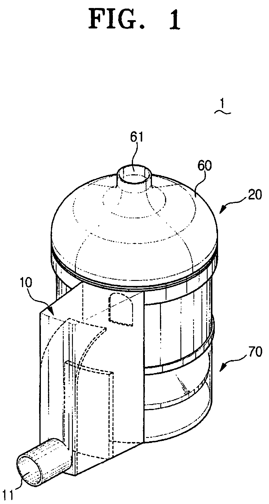
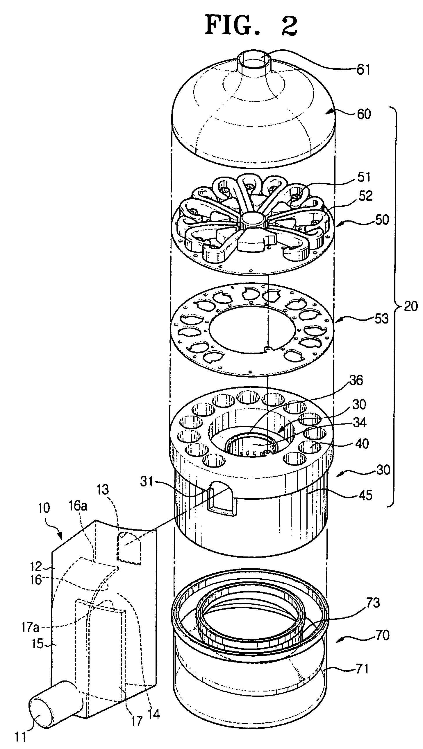
[0026]Referring to FIGS. 1 and 2, a multi-cyclone apparatus according to an embodiment of the present invention includes a first collecting unit 10, a cyclone body 20 and a contaminant receptacle 70.

[0027]The first collecting unit 10 separates relatively large-sized contaminants from an air as entering through an air suction po...


PUM

PropertyMeasurementUnit
distanceaaaaaaaaaa
heightaaaaaaaaaa
shapeaaaaaaaaaa

Abstract

A multi-cyclone apparatus is capable of separating and collecting contaminants by three stages. The multi-cyclone apparatus has a first collecting unit which separates large-sized contaminants from an air which is drawn through an air suction port, a cyclone body comprising a second cyclone which is communicated with the first collecting unit and separates middle-sized contaminants from the drawn air, and a plurality of third cyclones arranged around the second cyclone and separate small-sized contaminants from the drawn air, an air discharge port communicated with the cyclone body, through which the air is discharged after passing through the third cyclones, and a contaminant receptacle provided to a lower end of the cyclone body, and collects contaminants separated from the second and the third cyclones.

Description

CROSS-REFERENCE TO RELATED APPLICATIONS[0001]This application claims the benefit of U.S. provisional application No. 60 / 665,942, filed Mar. 29, 2005, in the United States Patent & Trademark Office, and claims the benefit of Korean Patent Application No. 2005-39125, filed May 11, 2005, in the Korean Intellectual Property Office, the disclosure of both of which are incorporated herein by reference.BACKGROUND OF THE INVENTION[0002]1. Field of the Invention[0003]The present invention relates to a vacuum cleaner. More particularly, the present invention relates to a multi-cyclone apparatus capable of sequentially separating contaminants from a drawn air by a plurality of stages and a vacuum cleaner having the same.[0004]2. Description of the Related Art[0005]A conventional cyclone apparatus is constructed such that, as a vacuum cleaner draws in contaminant-entrained air from a surface being cleaned with a suction force generated from a motor assembly, the cyclone apparatus separates cont...

Claims


Application Information

Patent Timeline
Patent Type & Authority Patents(United States)
IPC IPC(8): B01D45/12B01D50/00
CPCA47L5/362A47L9/102A47L9/1625A47L9/1641A47L9/165A47L9/1658A47L9/1666Y10S55/03A47L9/16A47L9/10
Inventor OH, JANG-KEUNHAN, JUNG-GYUN
Owner SAMSUNG GWANGJU ELECTRONICS CO LTD
Learn More