
Blade supporting apparatus in wiper apparatus

a technology of supporting apparatus and wiper, which is applied in the direction of vehicle maintenance, vehicle cleaning, domestic applications, etc., can solve the problems of large size, complex structure of supporting member, and deterioration of the smooth oscillation of the wiper blade, so as to facilitate the mounting operation. , the effect of simple and easy operation

Inactive Publication Date: 2009-01-06
MITSUBA CORP +1
View PDF17 Cites 32 Cited by
  • Summary
  • Abstract
  • Description
  • Claims
  • Application Information

AI Technical Summary

Benefits of technology

[0010]In accordance with the structure mentioned above, because the movement of the wiper blade with respect to the supporting member is performed in a linear contact state, whereby a sliding resistance is reduced, a smooth wiping operation can be performed, and it is possible to increase a durability.
[0020]Moreover, the structure can be made such that a first step portion engaging with the first lever in the window surface direction, so as to achieve a come-off prevention, and a second step portion engaging with the first lever in the lever length direction, so as to achieve a come-off prevention, are formed in the fitting and attaching portion of the support receiving body. In this manner, it is possible to fix the support receiving body to the wiper blade in a manner to prevent coming-off.

Problems solved by technology

As a result of the structure of the wiper blade in the related art, when the wiper blade oscillates in the window surface direction, as the support receiving body slides within the supporting concave portion in a surface-to-surface contact manner, a sliding resistance is generated between the support receiving body and the supporting concave portion, and there is a risk that a smooth oscillation of the wiper blade is deteriorated, which is problematic.
Further, in this wiper apparatus, because each of the wiper arm fixing portion, the supporting concave portion and the support receiving body is structured as one unit in a connected state, there are problems that the wiper apparatus is deteriorated in design due to an exposure of the supporting member.
In addition, a structure of the supporting member becomes complex and large sized.

Method used


Image

  • Blade supporting apparatus in wiper apparatus
  • Blade supporting apparatus in wiper apparatus
  • Blade supporting apparatus in wiper apparatus

Examples


second embodiment

[0076]That is, in a structure in accordance with a second embodiment, shown in FIGS. 11(A) and 11 (B), a through hole 16a for fixing a stabilizer 17 to a base end side is opened in a portion of an arm piece 16 corresponding to a stabilizer 17 mounting portion. Another through hole (a second through hole)16b is opened so as to be positioned in more leading end side than the through hole 16a. On the other hand, a protruding portion 17b protruding toward an upper side from an upper surface of an upper piece portion 17a is integrally formed in the stabilizer 17. Further, the structure is such that a positioning and an oscillation prevention of the stabilizer 17 with respect to the arm piece 16 are carried out by fitting the protruding portion 17b into the arm piece second through hole 16b.

third embodiment

[0077]In a variation, in a structure in accordance with a third embodiment, shown in FIGS. 11(C) and 11(D), a through hole 18a in an arm piece 18, for fixing a stabilizer 19 to a base end side, is opened in a portion corresponding to a stabilizer 19 mounting portion. A protruding portion 18b protruding downwardly is formed so as to be positioned at a more leading end side than the through hole 18a. On the other hand, a through hole 19b is opened in an upper piece portion 19a in the stabilizer 19, whereby the structure is made such that a positioning and an oscillation prevention of the stabilizer 19 with respect to the arm piece 18 are carried out by fitting the protruding portion 18b at the arm piece 18 side into the through hole 19b at the stabilizer 19 side.

[0078]As mentioned above, the arm piece and the stabilizer can provide the mutually positioning and oscillation preventing means by forming the engagement portions which are engaged with each other in a state of being displace...


PUM


Abstract

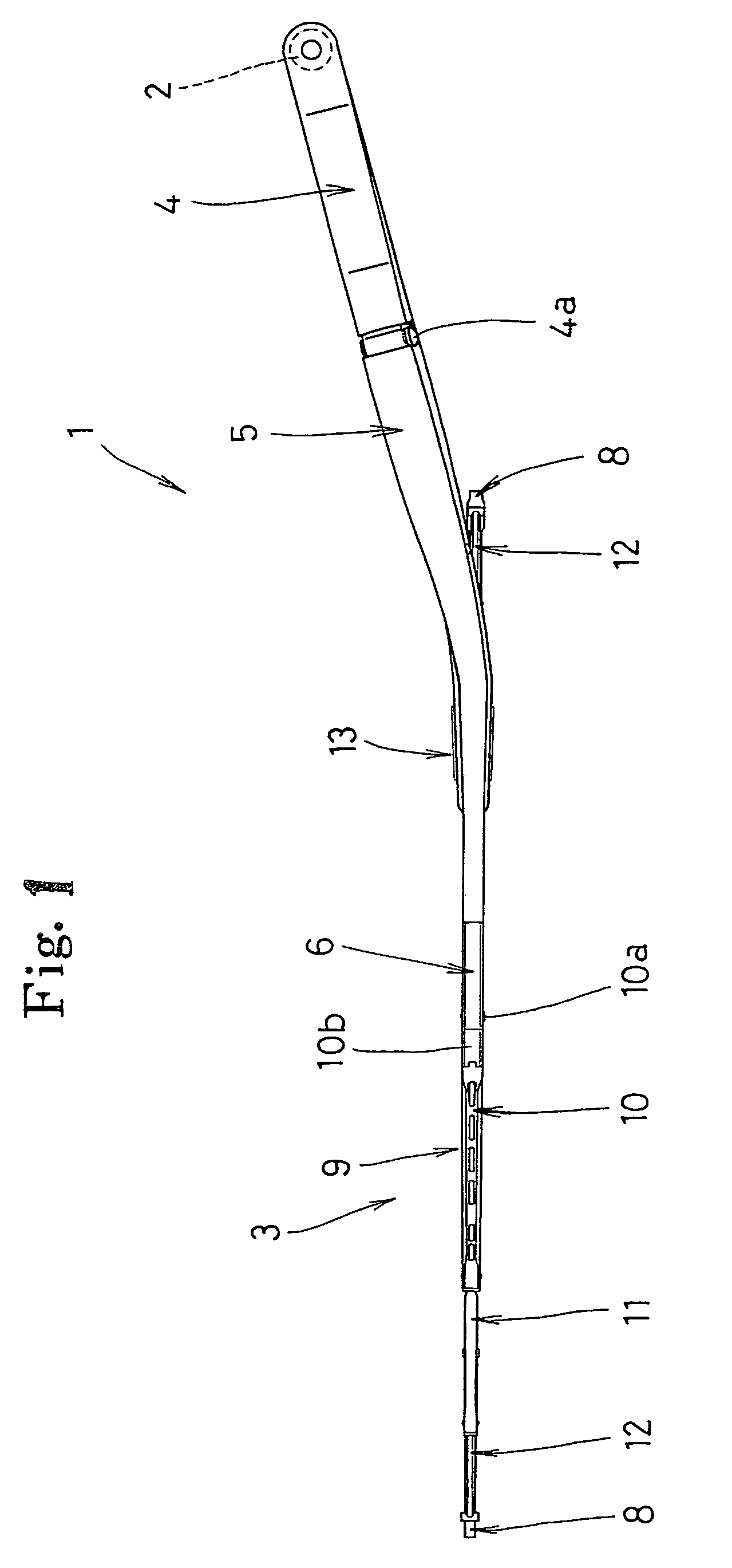
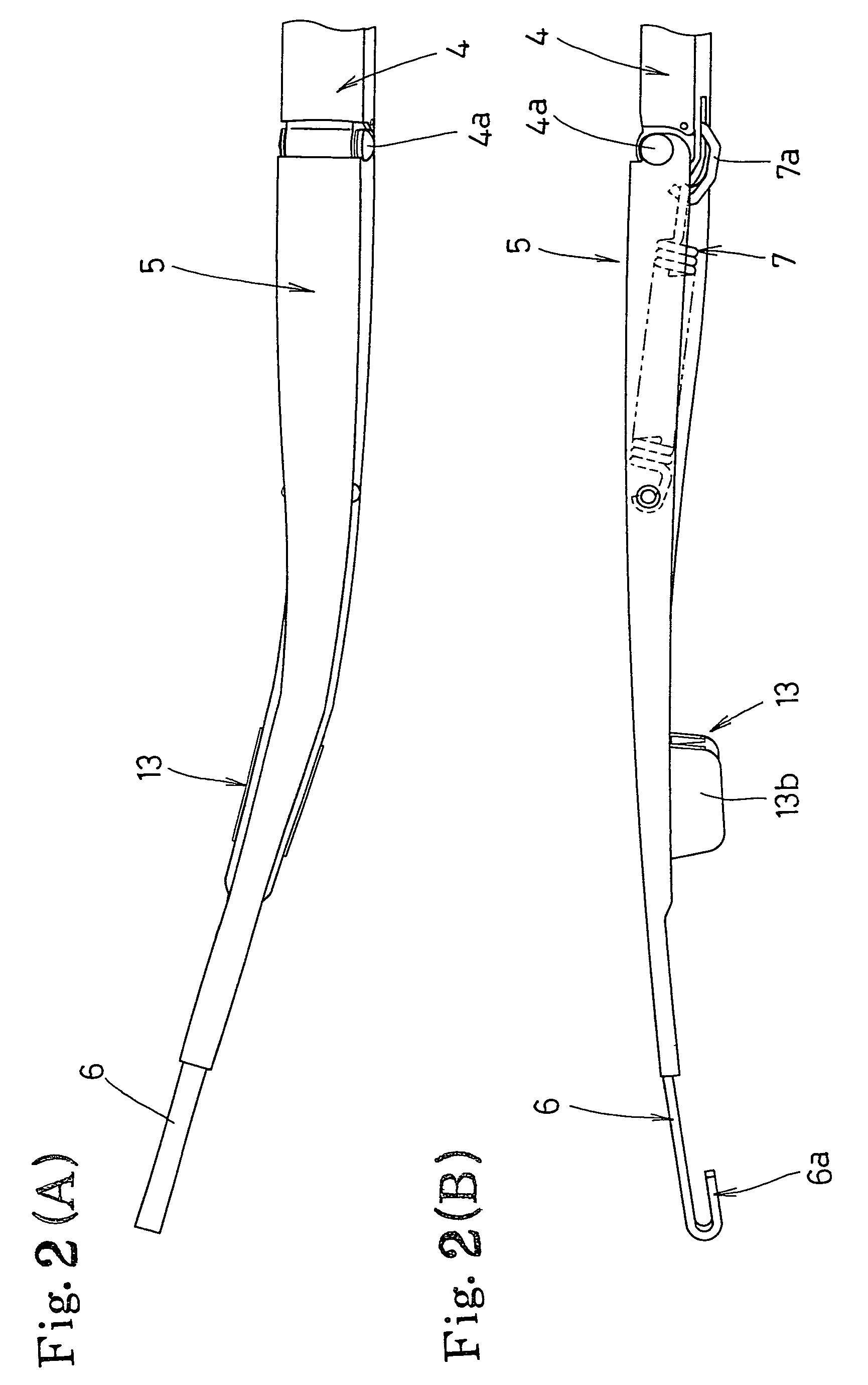
In a structure in which a middle portion of a wiper blade is pivoted to a leading end portion of a wiper arm via a pivot substantially orthogonal to an arm length direction so as to freely oscillate, and a supporting member supporting a portion closer to a wiper shaft than the middle portion of the wiper blade is provided in the wiper arm, the structure reduces a sliding resistance which occurs due to a movement of the wiper blade toward and away from a window surface. A stabilizer has an upper piece portion and a pair of side piece portions, a supporting concave portion supporting a wiper blade in an outward fitting manner is formed, and a plurality of ribs which extend toward the window surface are formed on inner surfaces of the side piece portions, thereby being in linear contact with outer surfaces of side piece portions of a support receiving body which is fitted to a first lever terminal end portion of the wiper blade.

Description

[0001]This application is a national stage application of PCT / JP03 / 01146 filed Feb. 4, 2003 which claims priority from JP 2002-35755 filed Feb. 13, 2002 and JP 2002-261942 filed Sep. 6, 2002, the disclosures of which are incorporated in their entirety herein by reference thereto.BACKGROUND OF THE INVENTION[0002]1. Technical Field[0003]The invention relates to a technical field of a blade supporting apparatus in a wiper apparatus which is equipped in a vehicle such as a private car, a truck, a bus or the like.[0004]2. Description of Related Art[0005]In general, in this kind of wiper apparatus, there is a structure such that a wiper blade provided in a leading end portion of a wiper arm, reciprocates forward and reverse so as to wipe a window surface on the basis of the normal and reverse rotation of a wiper shaft integrally mounted to a base end portion of the wiper arm. In this wiper apparatus, the structure is generally made such that a middle portion of the wiper blade is pivoted ...

Claims


Application Information

Patent Timeline
Patent Type & Authority Patents(United States)
IPC IPC(8): B60S1/40B60S1/32B60S1/34B60S1/38
CPCB60S1/3497B60S2001/3813B60S2001/3815
Inventor HARA, TAKESHISUZUKI, TAKEOKAGAWA, MAMORUKOGUCHI, SHUNICHI
Owner MITSUBA CORP
Learn More