
Battery management and equalization system for batteries using power line carrier communications

a technology of battery management and equalization system, which is applied in the direction of charging equalization circuit, transportation and packaging, and charging arrangements for several simultaneous batteries, can solve the problems of adding another level of complexity to accurate battery management, and achieve the effect of enhancing the battery charging system, facilitating plc link, and significant effect on cost-control related to battery warranties

Active Publication Date: 2008-12-30
POWER TECH HLDG LLC
View PDF19 Cites 77 Cited by
  • Summary
  • Abstract
  • Description
  • Claims
  • Application Information

AI Technical Summary

Benefits of technology

The invention is a battery management system that monitors various parameters, such as battery voltage, temperature, and current, to determine the state of charge and health of the battery. It uses individual measurement and equalization nodes placed on each battery cell, which communicate over an electrically isolated network. The system can be used in both stationary and mobile applications, and it provides data to improve the operation of batteries in electric or hybrid vehicles. The system is powered by a central power supply and can be easily expanded or reconfigured as needed. It also utilizes a DC equalization bus circuit and a PLC communications link for bi-directional communication between the battery management system and the bulk charger, which eliminates the need for additional cables and connectors. The system can help control battery charging and prevent premature battery failure, and it can also predict the end of battery life. Overall, the invention improves battery management and helps prolong battery life.

Problems solved by technology

Batteries, which have been configured in a series or parallel configuration, add another level of complexity to accurate battery management.

Method used


Image

  • Battery management and equalization system for batteries using power line carrier communications
  • Battery management and equalization system for batteries using power line carrier communications
  • Battery management and equalization system for batteries using power line carrier communications

Examples


Embodiment Construction

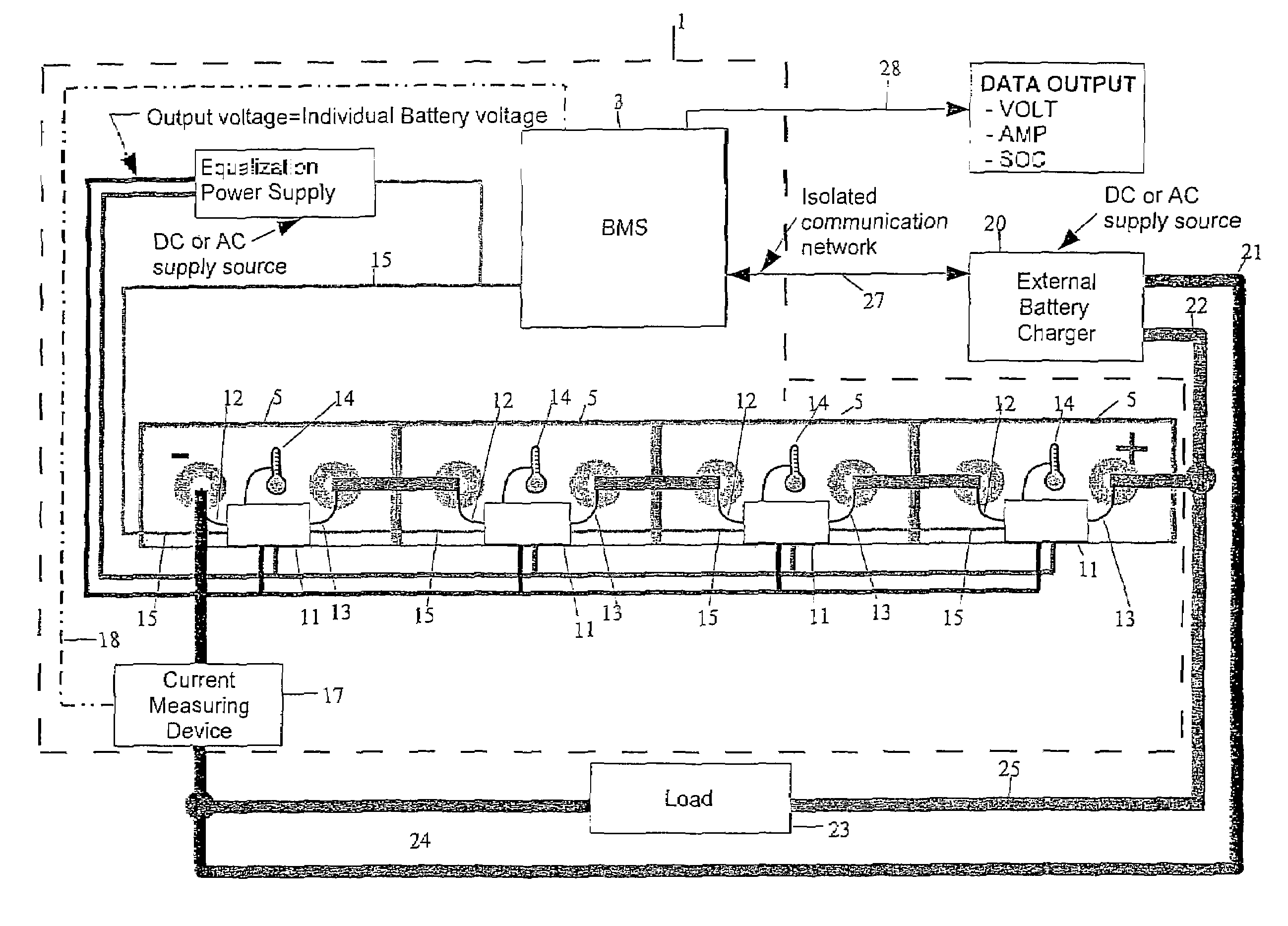
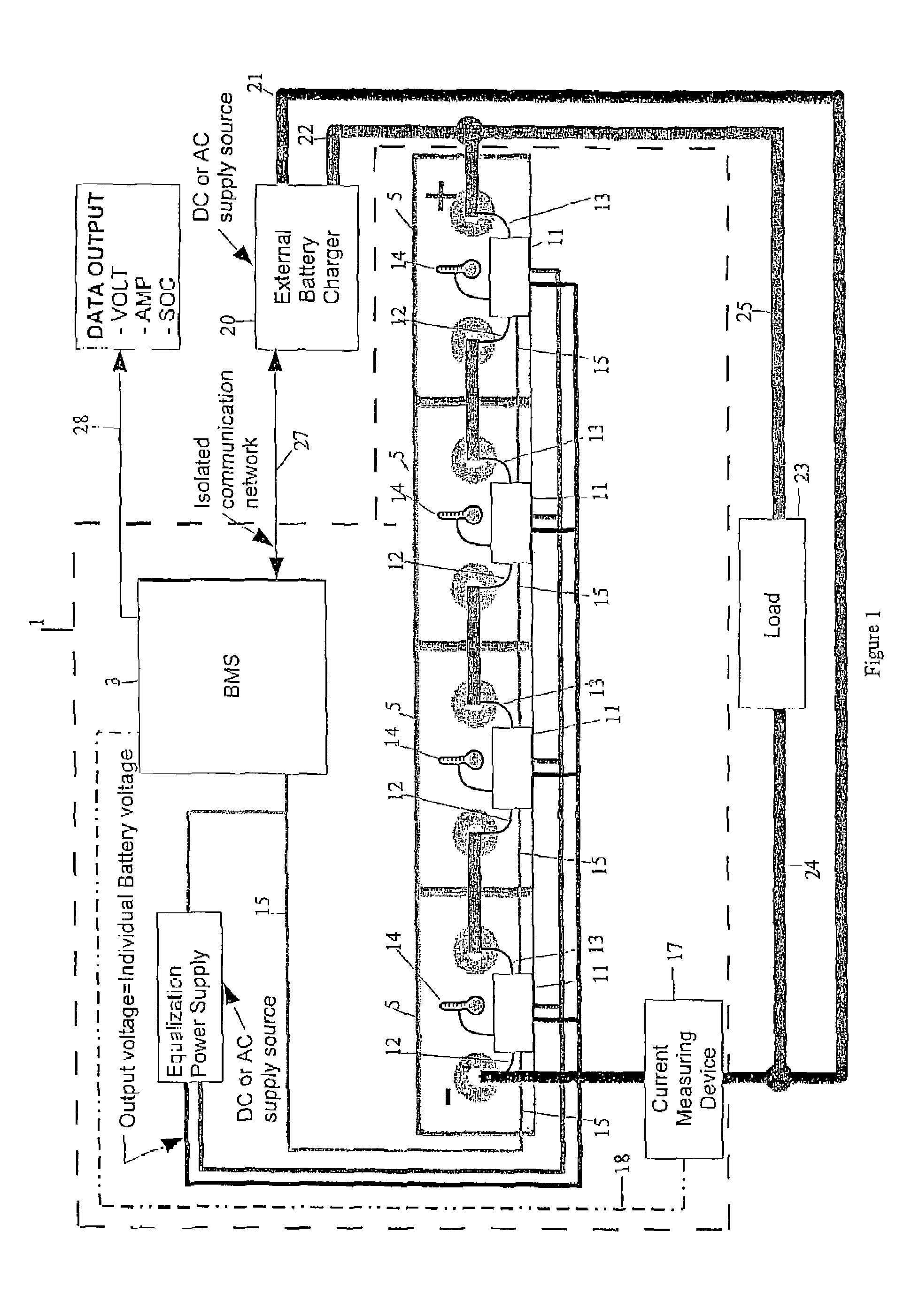
[0055]FIG. 1 is a block diagram of the battery management and equalization system of this invention. The battery pack 1 is encircled within a dashed line border; it contains several batteries 5 with individual measurement and equalization nodes 11, a central battery management system (BMS), current measurement device 17, an equalization power supply 7, and a variety of lines and busses for communications within battery pack 1 as well as externally. External to battery pack 1 is bulk charger 20 with charging cables 21 and 22, and load 23 with battery cables 24 and 25; also shown is the isolated communications cable 27 between BMS 3 and bulk charger 20 as well as output data line 28 which can provide data such as battery pack voltage, current, and overall state of charge. The latter values are typically displayed to a driver of an electric or hybrid vehicle or to a fork lift driver.

[0056]Bulk charger 20 can be powered by AC mains or by an AC or DC source which may be on-board a vehicl...


PUM


Abstract

A battery charging system uses power line carrier communications, for communicating battery state information associated with charging batteries, between a battery charger and a battery management system (BMS) located on the battery or battery pack. The power line carrier includes transmitters and receivers transmitting and receiving battery state information, such as current, voltage and temperature, as digital signals on existing cable conductors located between the battery / battery pack and the battery charger. The battery management system (BMS), which is physically located on the battery pack, receives the information from the power line carrier, in order to measure a variety of parameters relating to charging the battery, which may be a motor vehicle battery or a battery for operating machinery, such as fork lifts, bulldozers and other earth moving and product transportation vehicles.

Description

CROSS REFERENCE TO RELATED APPLICATIONS[0001]This application claims the benefit, Under 35 U.S.C. 119(e) of U.S. Provisional Application No. 60 / 637,887, filed Dec. 22, 2004 and U.S. Provisional Application No. 60 / 647,934, filed Jan. 31, 2005, which are hereby incorporated by reference.FIELD OF THE INVENTION[0002]The present invention is related to battery monitoring and charging. More particularly, the present invention is directed to batteries used individually or in a plurality of battery cells connected in a series or parallel configuration. This invention can be applied to batteries in mobile or stationary applications. The invention is applicable to the following battery configurations:[0003]Individual battery cells[0004]Batteries (comprised of cells)[0005]A battery pack comprised of a plurality of batteries electrically connected in series or parallel configuration or a combination of bothBACKGROUND OF THE INVENTION[0006]Those skilled in the art understand the challenges assoc...

Claims


Application Information

Patent Timeline
Patent Type & Authority Patents(United States)
IPC IPC(8): H02J7/00H02J7/02H02J7/04
CPCH02J7/0014Y02E60/10
Inventor AMBROSIO, JOSEPH MARIOSFAKIANOS, KONSTANTINOS
Owner POWER TECH HLDG LLC
Learn More