
Tool for setting expansion bolts

Inactive Publication Date: 2008-12-30
BP CORP NORTH AMERICA INC
View PDF24 Cites 5 Cited by
  • Summary
  • Abstract
  • Description
  • Claims
  • Application Information

AI Technical Summary

Benefits of technology

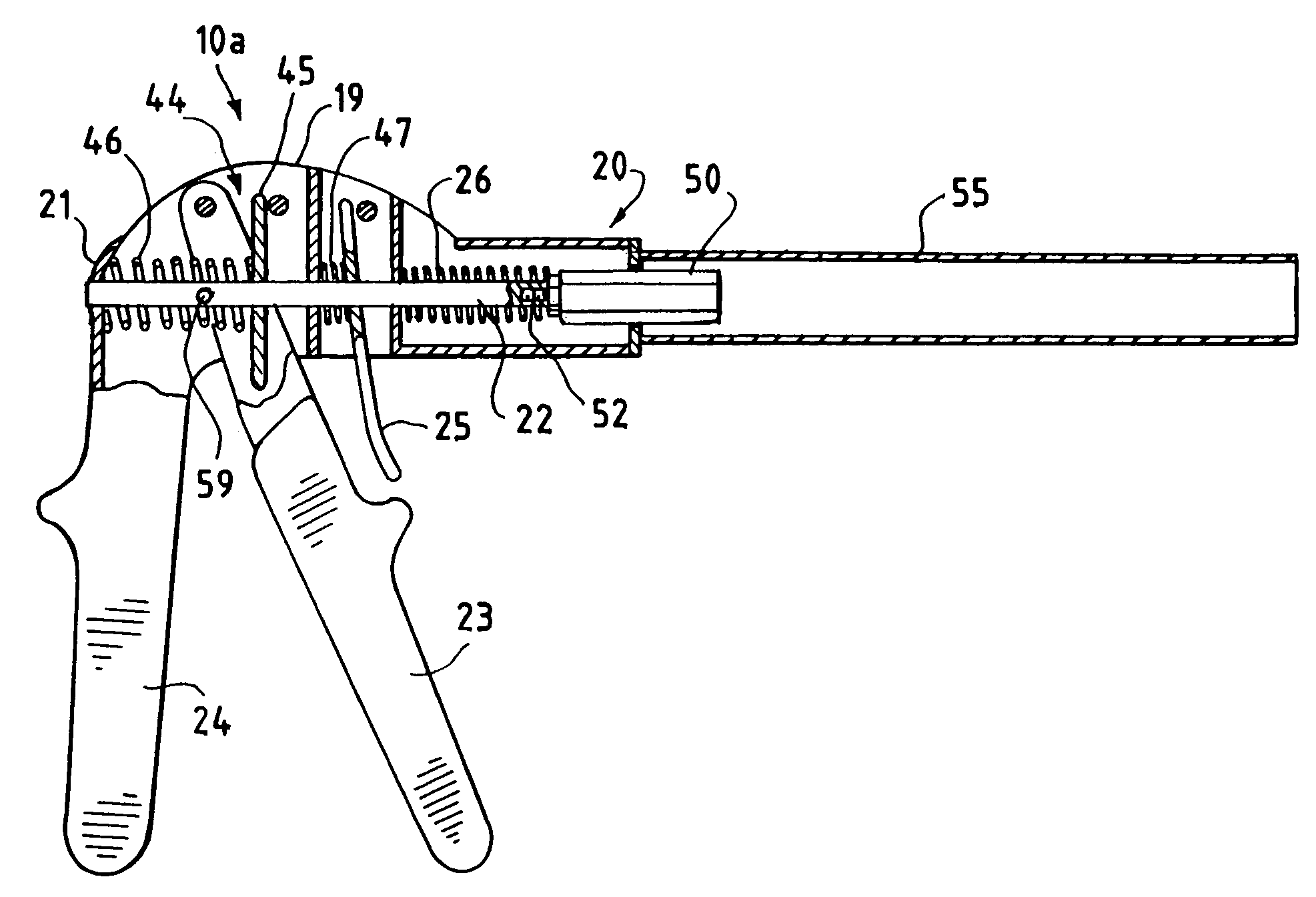
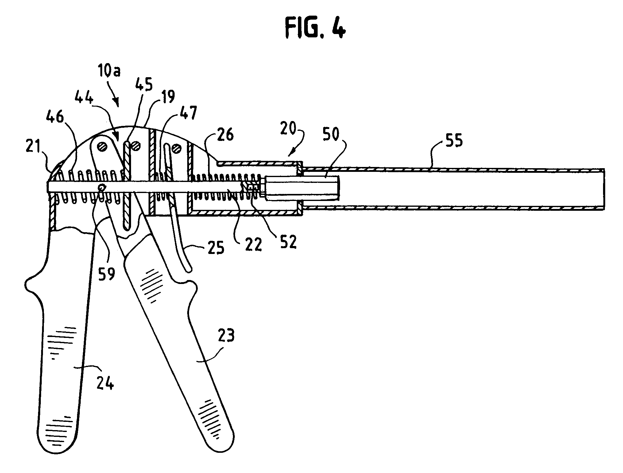
[0014]The present invention provides a tool and a method for installing an expansion bolt in a remote location where the expansion bolt is not readily accessible. Basically, the tool is capable of lowering the expansion bolt through aligned openings (e.g. openings in a arched tile and in the decking below) and then pulling the bolt upward to set the anchor without damaging either the threads on the bolt or the uppermost surface involved (e.g. upper surface of the arched tile).

Problems solved by technology

As will be recognized, such gripping tools are inefficient, especially where a relatively large number of bolts need to be installed, and can cause serious damage to the threads on the screw.
However, there are other installations that require the setting of a relatively large number of expansion bolts where these known, prior art guns can not be used; e.g. where (a) remote locations where the anchor portion of the expansion bolt is not readily accessible to the gun and (b) the screw of the expansion bolt is threaded along its entire length (i.e. has no head).
This presents a real problem since this type of tile is not a reliable support structure to which the necessary expansion bolts can be anchored.
Due to the relatively fragile nature of such ceramic or cement tiles, the forces exerted by the anchors on the tiles can easily crack and seriously damage the tiles during the operational life of the array which is obviously unacceptable.
In installations of this type, it is neither practical nor economical to remove and then replace the affected tiles to install the necessary expansion bolts.
It can readily be seen that none of the known prior art tools are capable of performing all of the necessary functions to set expansion bolts in such a remote environment.

Method used


Image

  • Tool for setting expansion bolts
  • Tool for setting expansion bolts
  • Tool for setting expansion bolts

Examples


Embodiment Construction

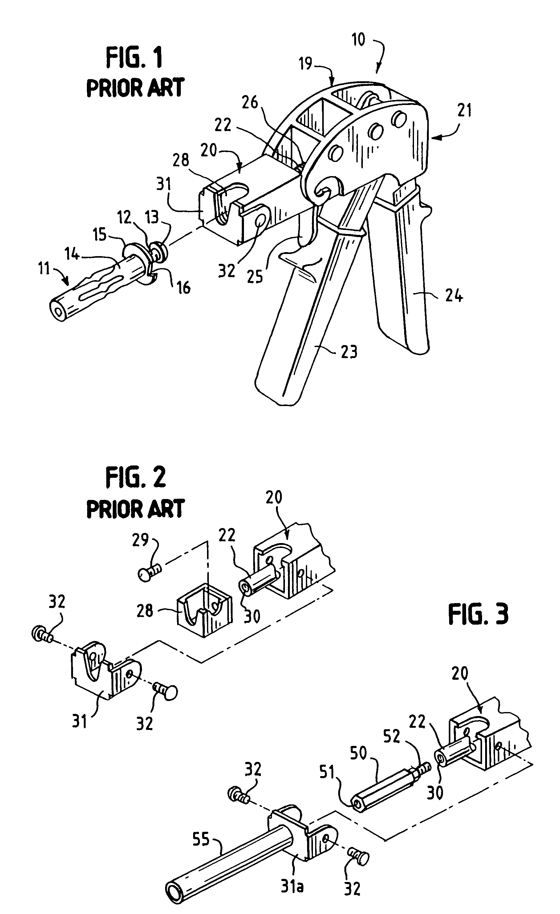
[0028]Referring now to the drawings, FIG. 1 illustrates a prior art, commercially available, tool 10 designed specifically for setting a common expansion bolt fastener 11. As will be recognized, expansion bolt 11 is of the type that is used to fasten objects to a surface such as a wallboard or the like. Bolt 11 is basically comprised of a central threaded element that is typically a screw 12 having a head 13 on the upper end thereof. Screw 12 is threaded into the lower end of expandable anchor portion 14, which, in turn, has a flange 15 with cleats 16 at its upper end. As will be understood, anchor portion 14 will expand outward from the screw as screw 12 is pulled upward towards flange 15.

[0029]The prior art expansion bolt setting tool or gun 10 (FIG. 1) is comprised of a housing 19 having a front portion 20 and a back 21. A rod 22 is slidably mounted for longitudinal movement within the housing. A ratchet mechanism (not visible in FIG. 1 but which will be described in more detail ...


PUM


Abstract

A tool and method for installing an expansion bolt in a remote location where the expansion bolt is not readily accessible. The tool is comprised of a housing having a rod with a puller element on one end slidably mounted in the housing. A barrel is attached to and extends from the front of the housing. The headless screw of an expansion bolt is loosely threaded into the puller element and the barrel of the tool and the bolt are lowered until the expandable anchor on the screw is in or below a hole in a remote support structure. A ratchet in the housing moves the puller within the housing to pull the screw upward while the lower end of the barrel abuts and holds the flange on the anchor portion against the support structure to set the expandable anchor.

Description

[0001]This application claims the benefit of U.S. Provisional Patent Application 60 / 471,320 filed on May 16, 2004.FIELD OF THE INVENTION[0002]The present invention relates to tool for setting expansion bolts and in one of its aspects relates to tool for setting expansion bolts in remote locations where the bolts are not readily accessible.BACKGROUND OF THE INVENTION[0003]An expansion or anchor bolt (hereinafter referred to as “expansion bolt”) is a well-known type of fastener that is used for securing objects to a board-like, support structure (e.g. decking, sheathing, wallboard, or the like). One of the most common of this type of fastener is one which has an expandable anchor mounted on the lower end of an elongated, central threaded member (i.e. bolt, screw, etc.; hereinafter referred to as “screw”).[0004]To secure this type of fastener in place, a hole is drilled through the support structure (e.g. board) and the lower end of the expansion bolt is passed through the hole until t...

Claims


Application Information

Patent Timeline
IPC IPC(8): B23P19/04B23P11/00B21J15/38B25B27/00F16B13/06
CPCB21J15/386B25B27/0007F16B13/061Y10T29/49963Y10T29/49915Y10T29/53987Y10T29/53896Y10T29/49938Y10T29/539Y10T29/53717
Inventor WARFIELD, DONALD B.
Owner BP CORP NORTH AMERICA INC
Learn More