
Apparatus for separating solids from flowing liquids

a technology of floating suspended solids and apparatus, which is applied in the direction of filtration separation, sedimentation settling tanks, separation processes, etc., can solve the problems of sheer volume of liquid to be handled in plants, too expensive to be used in the whole of a stormwater system, and unsatisfactory general results

Active Publication Date: 2008-12-16
CONTECH ENGINEERED SOLUTIONS
View PDF197 Cites 39 Cited by
  • Summary
  • Abstract
  • Description
  • Claims
  • Application Information

AI Technical Summary

Benefits of technology

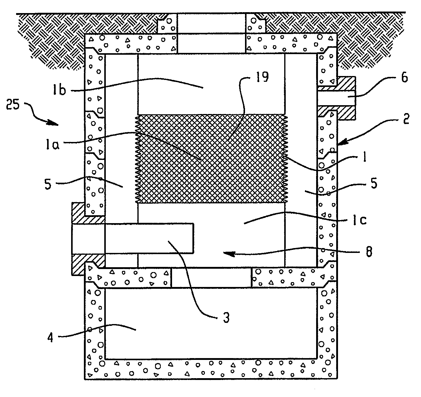
The invention is an apparatus for separating solid matter from a liquid stream. It includes a cylindrical separation panel with openings that remove solid material larger than a certain size from the liquid. The panel has deflective segments that prevent the openings from being blocked by larger particles. The apparatus also has a chamber where the liquid passes after passing through the separation panel. The technical effect of this invention is to provide a reliable and efficient way to separate solid matter from liquid streams.

Problems solved by technology

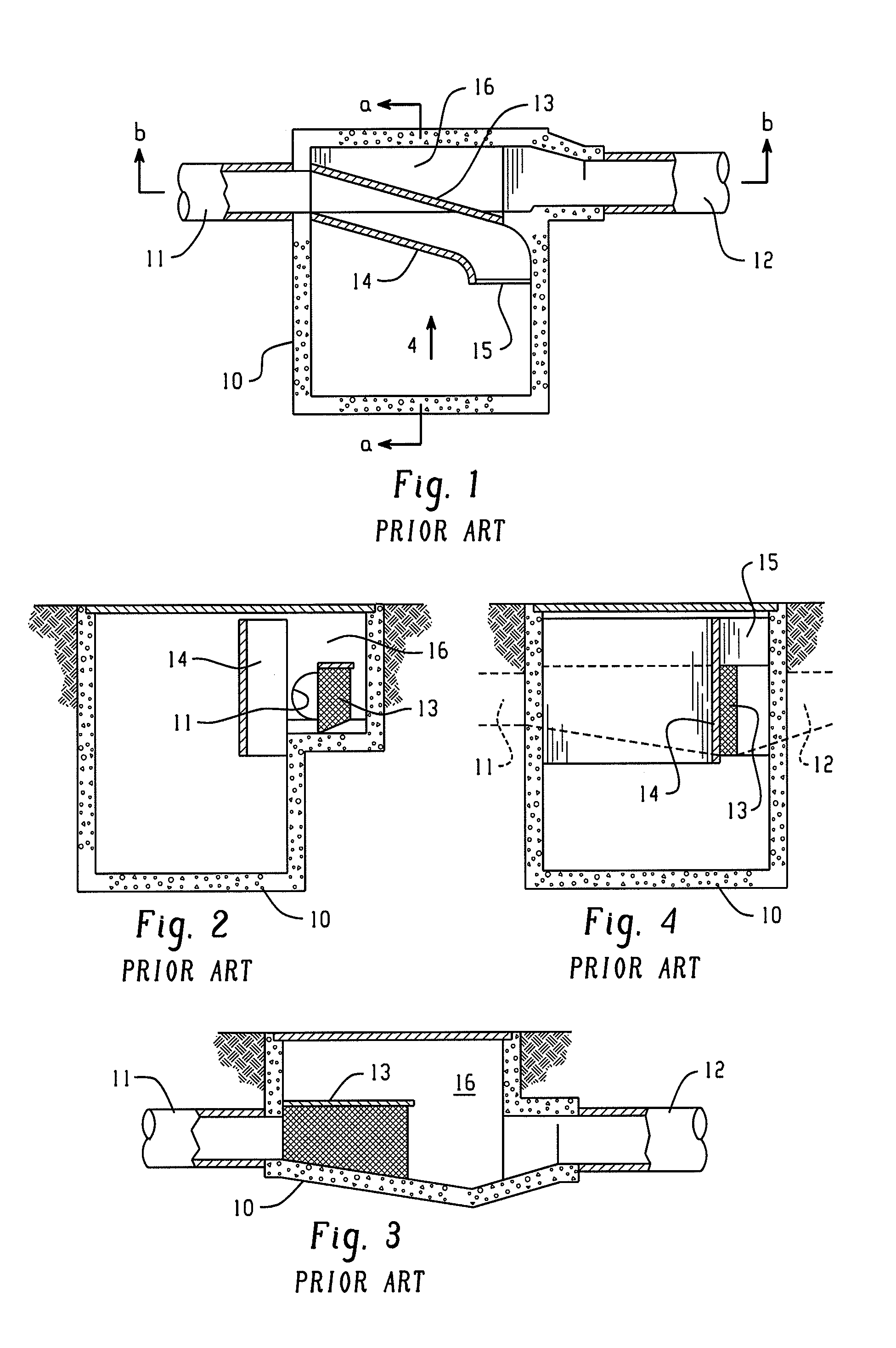
One method used is by having grates across outlets from the drains but these have generally been unsatisfactory because the size of the grate must be such as to enable water to pass even if material is held against the grate by water pressure so it has been necessary that the grate be of substantial opening size.
Whilst these can be efficient, they are too expensive to be used in the whole of a stormwater system.
A major difficulty with many sewage plants is the sheer volume of liquid to be handled.
To date, this has not been considered feasible.
This can cause difficulties where there are heavy rains which overload the system, as it is undesirable to permit raw sewage to pass to overflow.

Method used


Image

  • Apparatus for separating solids from flowing liquids
  • Apparatus for separating solids from flowing liquids
  • Apparatus for separating solids from flowing liquids

Examples


Embodiment Construction

[0042]Aspects of the invention relate to nonmechanical methods of and apparatuses for separating floating and suspended solids from flowing liquids.

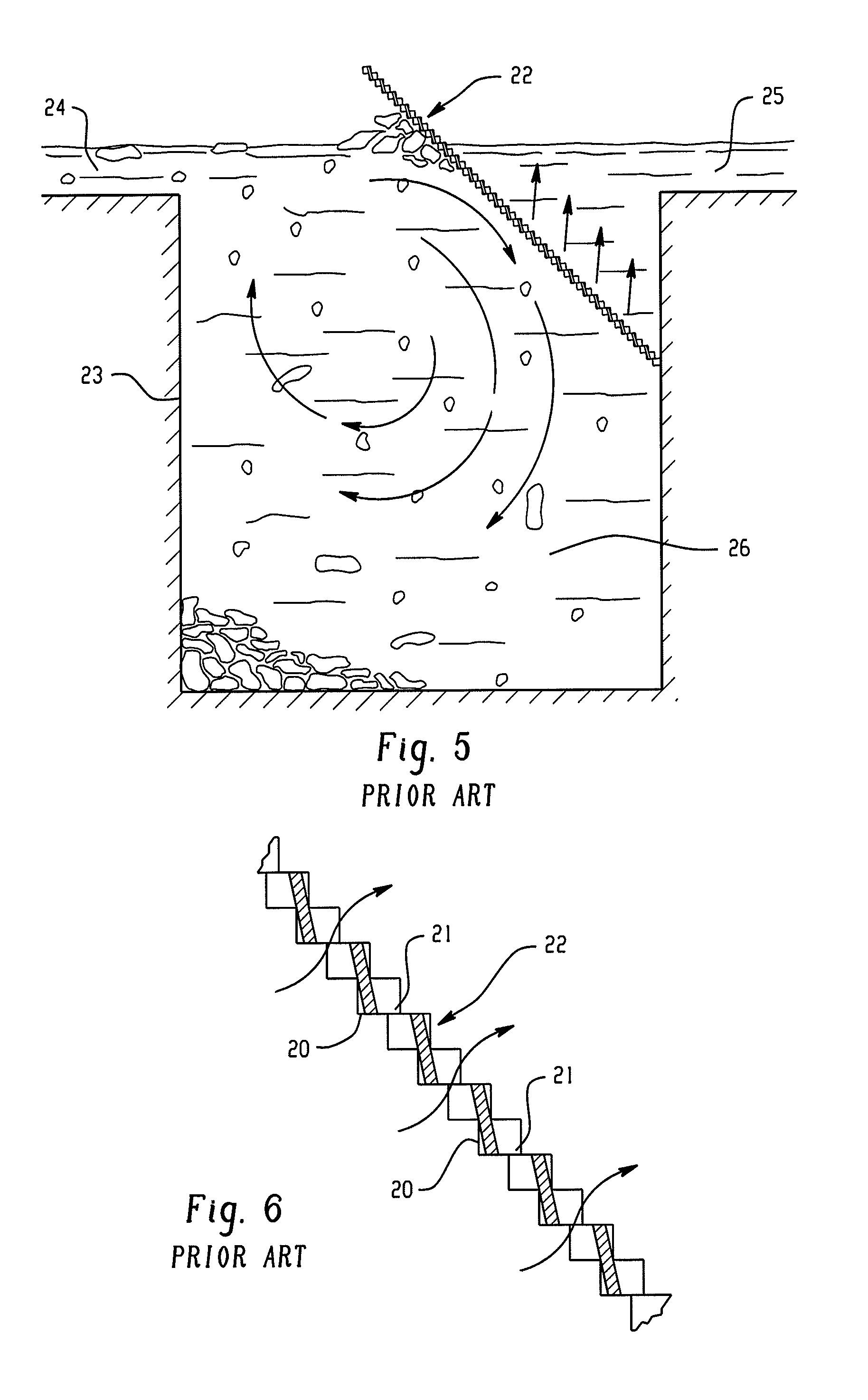
[0043]The apparatuses may include a means for the separation of solid matter from a liquid including a perforated separation panel into which the liquid may enter from below, and which prevents the passage of the solid matter of a size larger than a predetermined size characterized in that when solid matter becomes located against the panel, the flow of liquid along the face of the panel on which the solid matter is located will tend to cause it to move from the panel so that the panel is self cleaned and does not become obstructed by the solid matter.

[0044]The methods may include non-mechanical methods for separating solids from a flowing liquid by utilizing the energy of the flowing liquid from the bottom inlet, a separation panel in the path of the fluid flow and so arranged that the liquid is deflected thereby, which deflection causi...


PUM

PropertyMeasurementUnit
sizeaaaaaaaaaa
heightaaaaaaaaaa
volumeaaaaaaaaaa

Abstract

An apparatus for separating solid matter from a liquid stream, where the apparatus includes a generally cylindrical separation panel surrounding an interior space, which is oriented so as to have a substantially vertical longitudinal axis. The separation panel has a plurality of vertically and horizontally spaced openings which are adapted to remove solid material larger than a predetermined size from liquid passing through the separation panel. The apparatus also includes a chamber surrounding the separation panel and providing a chamber portion into which the liquid passes after passing through the separation panel. The apparatus may further include an inlet positioned below the separation panel, through which the liquid stream is delivered from a bottom opening of the separation panel to the interior space and which is arranged such that the liquid circulates about the axis so as to pass the separation panel, and an outlet extending from the chamber portion.

Description

CROSS-REFERENCES TO RELATED APPLICATIONS[0001]This application is related to U.S. patent application Ser. No. 08 / 934,078, filed Sep. 19, 1997, now U.S. Pat. No. 6,641,720, issued Nov. 4, 2003, which is a continuation-in-part of U.S. patent application Ser. No. 08 / 501,011, filed on Dec. 6, 1995, now abandoned, and U.S. patent application Ser. No. 08 / 750,706, filed on Mar. 24, 1997, now U.S. Pat. No. 5,788,848, issued Aug. 4, 1998, each of which is incorporated herein by reference. application Ser. No. 08 / 501,011 is a 371 under 35 U.S.C. § 365 of International Applications Nos. PCT / AU94 / 00061, filed Feb. 11, 1994 and application Ser. No. 08 / 750,706 is a 371 of PCT / AU95 / 00351, filed Jun. 16, 1995.BACKGROUND OF THE INVENTION[0002]This invention relates to methods of and apparatus for separating floating and suspended solids from a flowing liquid using continuous deflective separation, and particularly, but not solely to non-mechanical methods and apparatus.[0003]More generally, the inve...

Claims


Application Information

Patent Timeline
Patent Type & Authority Patents(United States)
IPC IPC(8): B01D29/66B01D35/22B01D36/04
CPCB01D21/0012B01D29/03E03F5/14
Inventor HEIST, JAMES A.DAVEY, ALEXZIEGLER, DAVID
Owner CONTECH ENGINEERED SOLUTIONS
Learn More