
Stretching apparatus and associated method

a technology for stretching apparatus and leg muscles, applied in the field of therapeutic machinery, can solve the problems of increased likelihood of injury, decreased flexibility, and decreased flexibility of the muscles, and achieve the effect of stretching the calves and taking up some of the muscle looseness

Inactive Publication Date: 2008-12-02
PISCIOTTANO MAURICE A
View PDF22 Cites 18 Cited by
  • Summary
  • Abstract
  • Description
  • Claims
  • Application Information

AI Technical Summary

Benefits of technology

The apparatus provides therapeutic stretching for both upper and lower leg muscles, improving flexibility and correcting foot flare, thereby reducing pain and joint stress by ensuring muscles are stretched over the leg joints.

Problems solved by technology

This is undesirable.
However, many people's muscles are in a condition of being inadequately stretched, with resultant pain, loss of motion, and increased likelihood of injury.
For other people, the stretching exercises performed may be inadequate or may be non-optimized, with the result that their muscles are inadequately stretched and of an undesirably low degree of flexibility.
It is also known that an excessive flare angle between the feet is undesirable.
An excessive flare can cause difficulty in walking and accelerated degradation of the leg joints, particularly the hip joint, since the head of the femur often cannot sit properly in the acetabulum.
Moreover, stretching of the leg muscles of a subject having an excessive foot flare often cannot be accomplished with a great degree of success since the leg muscles become misaligned with the leg joints during a stretch.
That is, the muscles are not stretched over the leg joints and rather are stretched at least partially at the sides of the leg joints, with the result that the muscles cannot be adequately stretched.

Method used


Image

  • Stretching apparatus and associated method
  • Stretching apparatus and associated method
  • Stretching apparatus and associated method

Examples


Embodiment Construction

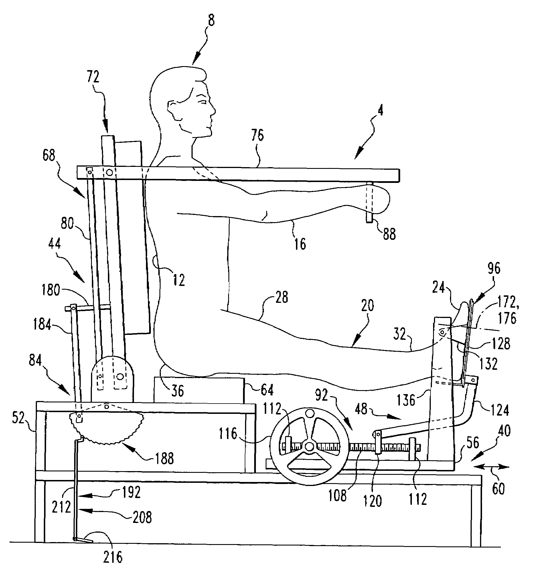
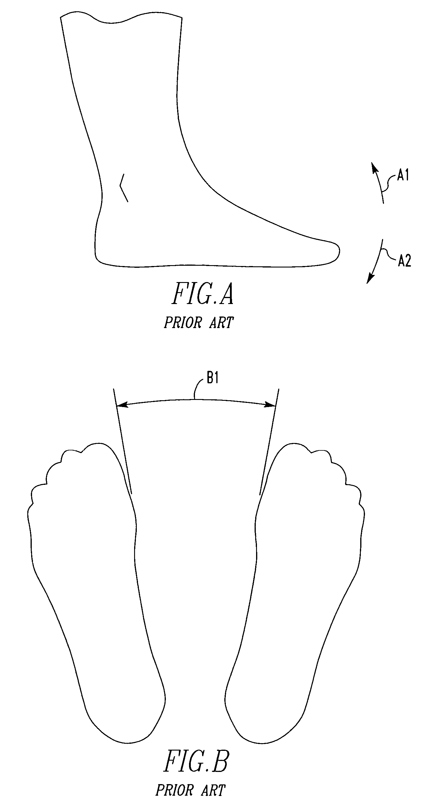
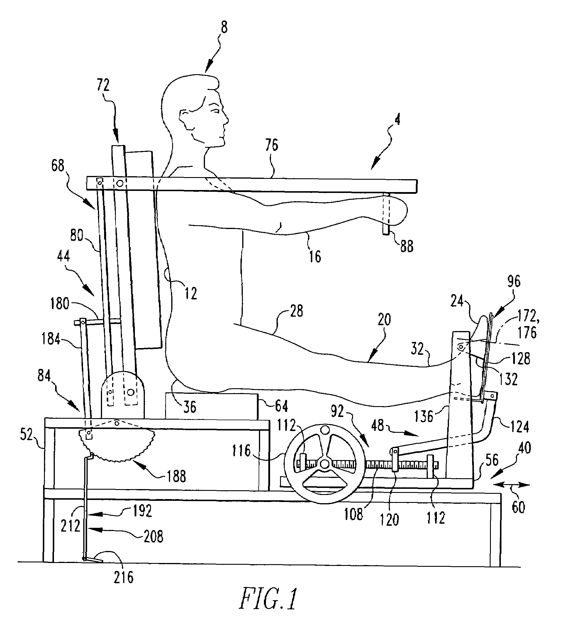
[0029]FIGS. A and B depict feet and are employed to describe certain terminology that will be employed herein in relation to the depicted feet. The exemplary feet are depicted as being human feet, it being understood that the teachings herein shall not be construed to be limited to a human subject. FIG. A depicts at the numeral A1 a direction of movement that will be referred to herein as being movement in a dorsal direction. In a general, movement of a foot in the dorsal direction will refer to movement of the front part of the foot that includes the toes in a direction generally toward the knee. Such movement in the foot in the dorsal direction typically will involve pivoting of the foot about the ankle. FIG. A similarly depicts at the numeral A2 movement in the plantar direction, which is a direction generally opposite the dorsal direction. Movement of a foot in the plantar direction typically will involve movement of the front of the foot that includes the toes in a direction ge...


PUM


Abstract

An improved stretching apparatus includes a movable back rest and a movable foot manipulator which, when employed together, can provide therapeutic stretching to the leg muscles of a subject. For instance, the improved device can stretch the calves, hamstrings, and other leg muscles. An improved method of employing a stretching apparatus to perform a therapeutic stretching operation on the leg muscles of a subject includes engaging a subject's outstretched legs with a foot manipulator of the stretching apparatus, engaging the subject's back with a back rest of the stretching apparatus, and pivoting the foot manipulator in a stretching direction to move the feet in a dorsal direction to provide stretching of at least some of the leg muscles. The method can additionally include returning the foot manipulator to its original position, incrementally moving the back rest to take up some of the muscular looseness created by the movement of the foot manipulator in the stretching direction, and again pivoting the foot manipulator in a stretching direction to perform an additional stretching operation.

Description

BACKGROUND OF THE INVENTION[0001]1. Field of the Invention[0002]The invention relates generally to therapeutic machinery and, more particularly, to an apparatus for stretching the leg muscles of a subject.[0003]2. Description of the Related Art[0004]The desirability of having flexible muscles is well documented. The flexibility of a muscle typically is proportional to the strength or power of the muscle. As the relative flexibility of a person's muscles increases, the likelihood of injury to the person from day-to-day activities is correspondingly reduced. Increased muscular flexibility additionally provides for pain reduction and an increased range of motion, all of which are desirable.[0005]A typical muscle includes layers of muscle tissue and layers of fascia tissue, with lubrication typically being provided between adjacent layers of muscle tissue and fascia tissue. As tissue ages, the tissue tends to shrink, i.e., shorten, and layers of muscle tissue can become adhered to adjac...

Claims


Application Information

Patent Timeline
Patent Type & Authority Patents(United States)
IPC IPC(8): A63B26/00A63B23/08
CPCA63B23/04A63B2023/006A63B2208/0238Y10S482/907
Inventor PISCIOTTANO, MAURICE A.
Owner PISCIOTTANO MAURICE A
Learn More