
Machine for fitting and removing tires and wheel rims for vehicles

a technology for tires and wheels, applied in the field of vehicles' tires and wheel rims, can solve the problems of increasing the overall complexity of the machine, the risk of tool jamming between the tire and the rim, and the known machine is susceptible to upgrading, so as to achieve safe use, simple structure, and practical implementation

Inactive Publication Date: 2008-11-25
GIULIANO GROUP
View PDF10 Cites 9 Cited by
  • Summary
  • Abstract
  • Description
  • Claims
  • Application Information

AI Technical Summary

Benefits of technology

"The present invention is a machine for removing and fitting tires and wheel rims for vehicles. It includes a supporting structure for clamping and rotating the rim of a vehicle wheel around a rotation axis. The machine also has an operating unit that is associated with the supporting structure and includes an operating head for fitting and removing a tire onto / from the rim. The machine has an actuator element for operating the sideways movement of the operating head and guide means for the sideways movement along a curvilinear direction between a first position and a second position. The technical effect of this invention is to provide a machine that can easily and efficiently remove and fit tires and wheel rims for vehicles."

Problems solved by technology

These tire changing machines have a number of drawbacks, among which the not always perfect grip of the tool for the removal on the bead, with the risk of the tool jamming between the tire and the rim.
These known machines are however susceptible to upgrading, especially in order to ensure a correct and easy removal of the tire while providing, at the same time, more simple structure and function.
The need to control and combine several actuators during the removal stage in fact calls for the presence of a computer suitable for coordinating operations, with consequent increase in the overall complexity of the machine.

Method used


Image

  • Machine for fitting and removing tires and wheel rims for vehicles
  • Machine for fitting and removing tires and wheel rims for vehicles
  • Machine for fitting and removing tires and wheel rims for vehicles

Examples


Embodiment Construction

)

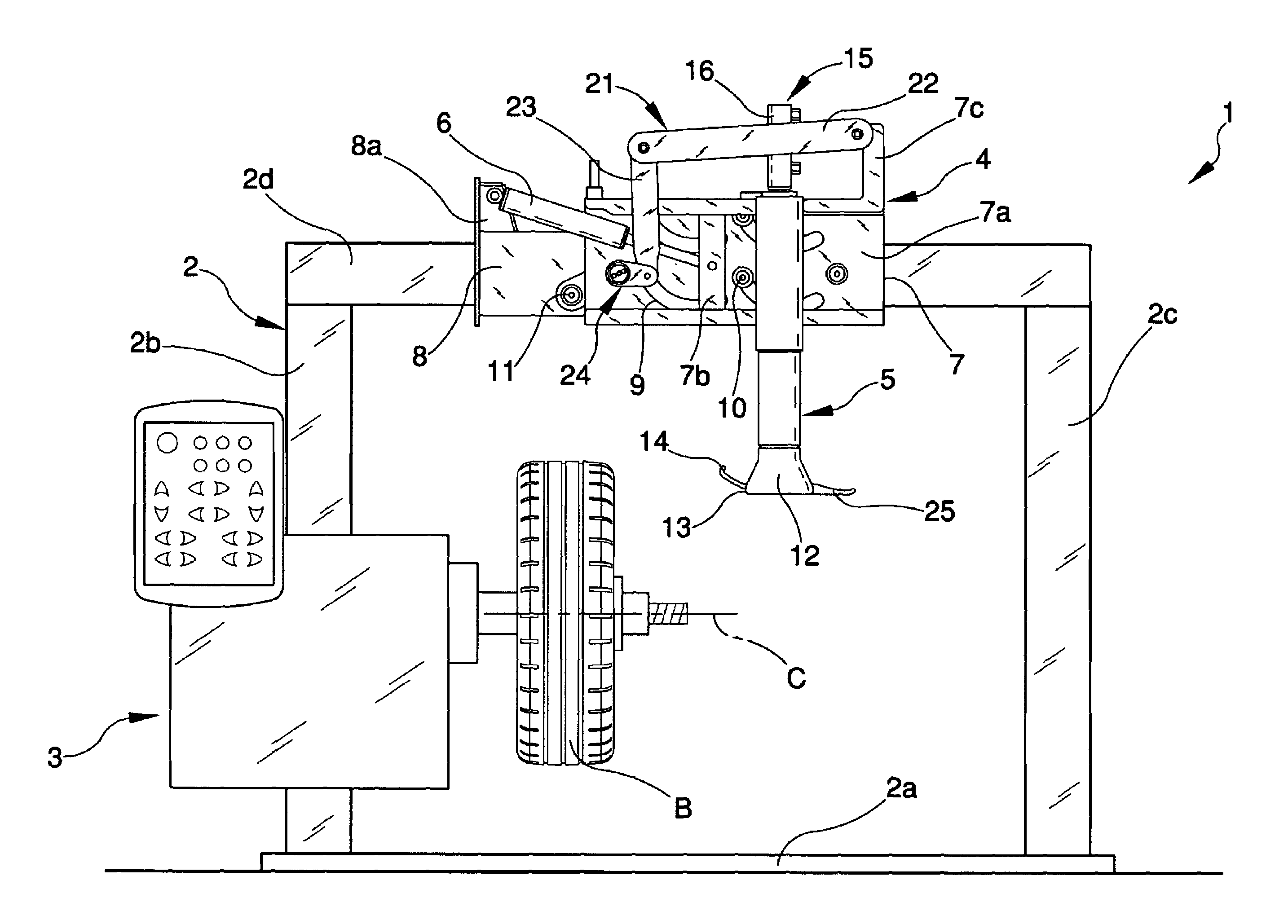
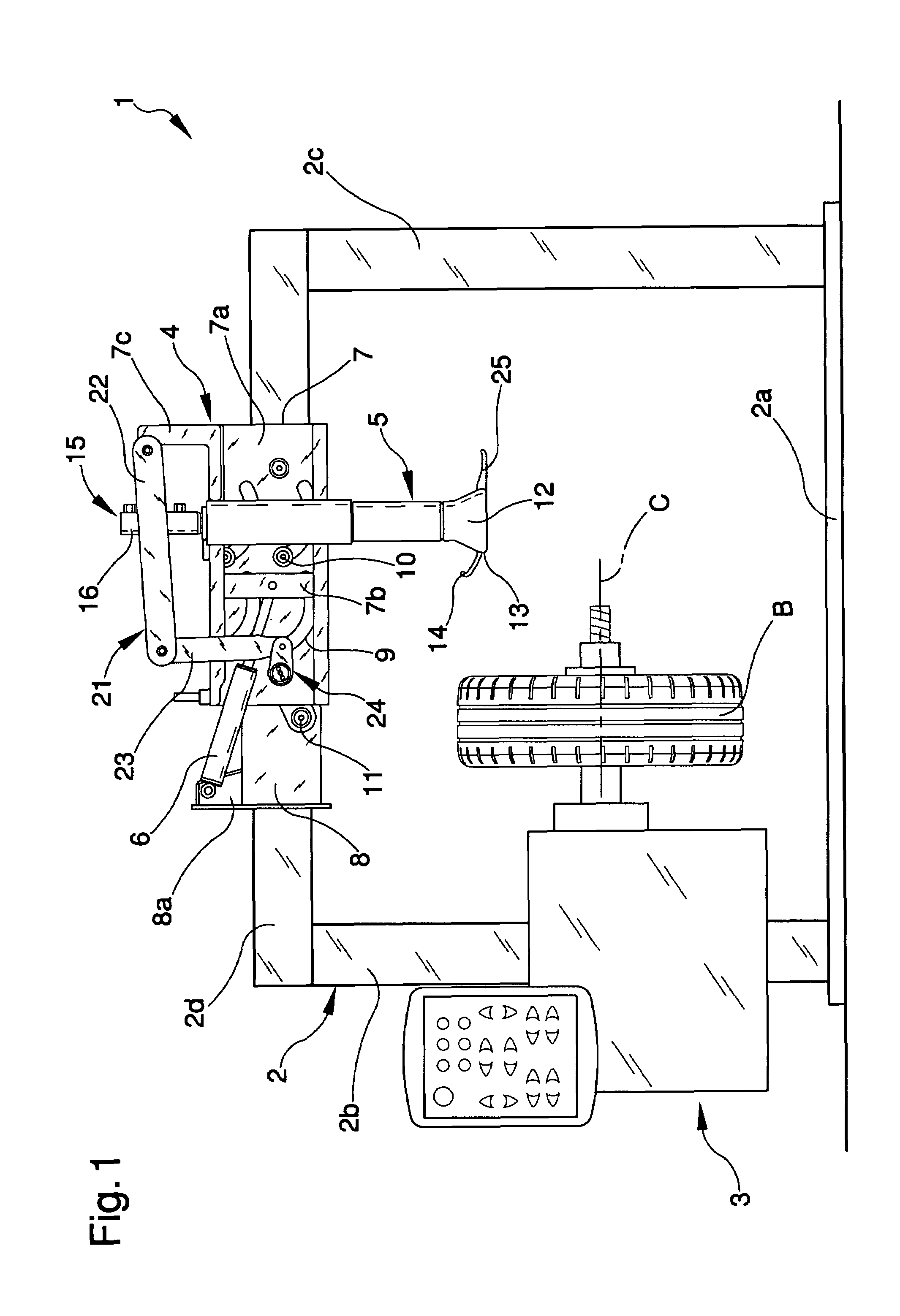
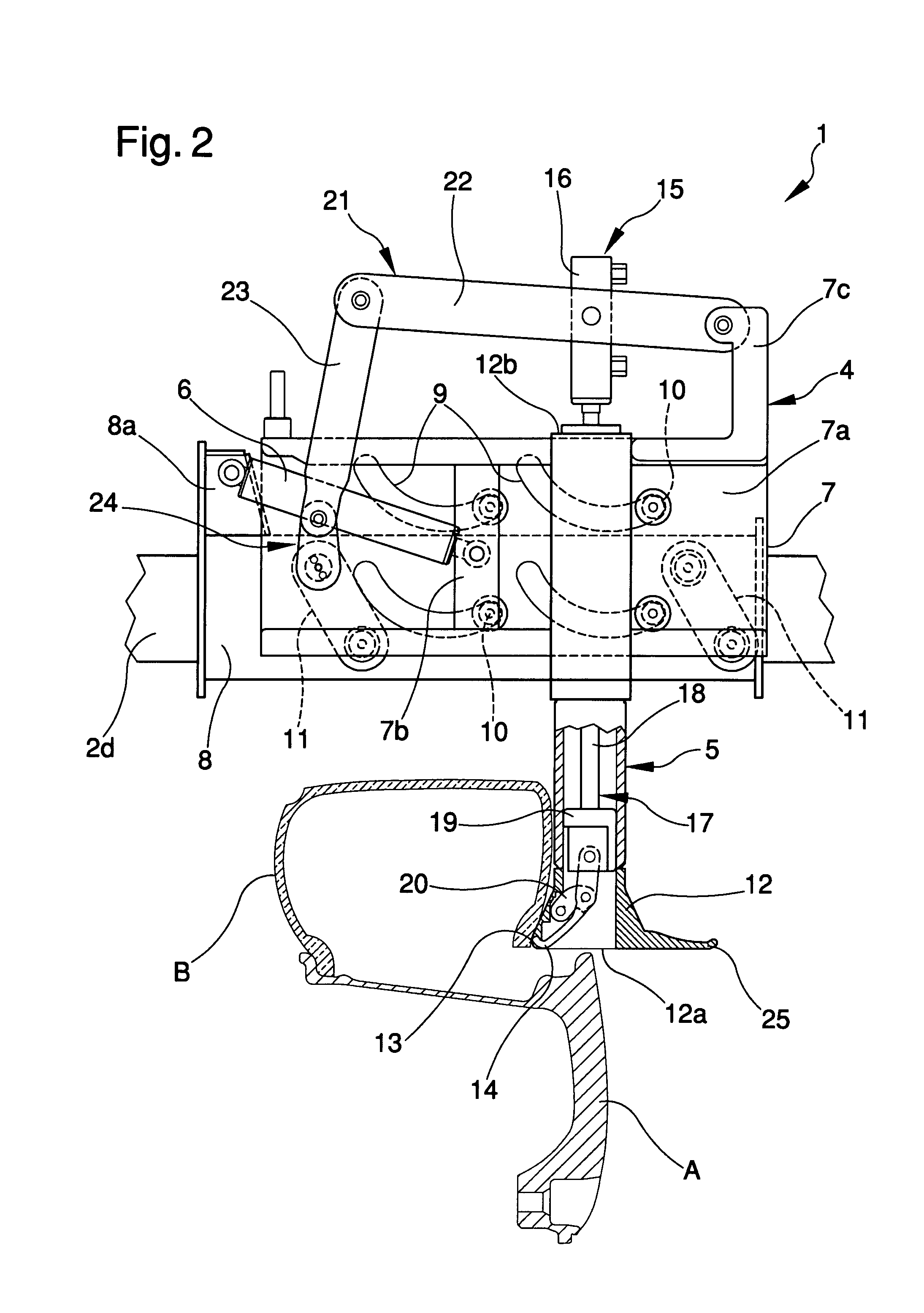
[0021]With particular reference to such figures, a machine for fitting and removing tire and wheel rims for vehicles has been globally indicated by 1.

[0022]The machine 1 includes a supporting structure 2 for supporting a clamping and rotating device 3 for clamping and rotating a rim A onto / from to mount / remove a tire B around a substantially horizontal rotation axis C.

[0023]An operating unit 4 is movably supported by the structure 2 and is provided with an operating head 5 for mounting and / or removing the tire B onto / from the rim A.

[0024]In particular, the structure 2 includes a base 2a from which elevate a first and a second upright 2b and 2c distanced from each other and supporting a transom 2d arranged above the clamping and rotating device 3 and to which the operating unit 4 is movably associated. The clamping and rotating device 3 is supported by the first upright 2b and can be moved therealong by a height adjustment device, such as a motor device, a fluid actuator, or the lik...


PUM


Abstract

A machine for removing and fitting tires and wheel rims for vehicles includes a supporting structure of clamping and rotating device for clamping and rotating the rim of a vehicle wheel around a rotation axis, at least one operating unit which is movably associated with the supporting structure and which includes at least one operating head for fitting and removing a tire onto / from the rim provided with a pushing body for pushing at least one portion of the side surface of the tire and with a grip tool for gripping at least one section of the tire bead, an actuator element for operating the sideways movement of the operating head with respect to the structure and guide means of such sideways movement along a substantially curvilinear direction between a first position, in which the operating head is substantially close to the clamping and rotating device and a second position, in which the operating head is substantially moved away from the clamping and rotating device.

Description

FIELD OF THE INVENTION[0001]The present invention refers to a machine for fitting and removing tires and wheel rims for vehicles.BACKGROUND OF THE INVENTION[0002]As is known, vehicle wheels generally include a metal rim having along the perimeter ring-shaped turn-ups between which the end portions, so-called “beads” of an elastic tire, are inserted fast up and adhered.[0003]The use is currently known of so-called “tire changing” machines for removing and fitting tires from and onto their relevant rims for carrying out, for example, inner tube maintenance, repair or replacement jobs.[0004]Such “tire changing” machines can be, for example, of the automatic type, and are essentially composed of a supporting frame for a clamping and rotating device for clamping and rotating the rim of a wheel onto / from which the tire must be fitted / removed and of an operating unit having an operating head for fitting and removing the tire.[0005]Such operating head is, generally, equipped with a tool for...

Claims


Application Information

Patent Timeline
Patent Type & Authority Patents(United States)
IPC IPC(8): B60C25/138
CPCB60C25/138B60C25/0578B60C25/0518
Inventor BONACINI, MAURIZIO
Owner GIULIANO GROUP
Learn More