Process of detection of a dive start in a dive computer

a dive start and computer technology, applied in the field of detecting the start of a dive, can solve the problems of significant drawbacks, significant consequences as regards the manufacturing cost of the device, and similar drawbacks, and achieve the effect of increasing precision

Active Publication Date: 2008-11-11
ETA SA MFG HORLOGERE SUISSE
View PDF11 Cites 2 Cited by
  • Summary
  • Abstract
  • Description
  • Claims
  • Application Information

AI Technical Summary

Benefits of technology

[0028]These additional steps also increase precision as to the stored reference pressure value by multiplying the updating possibilities with respect to the basic method.

Problems solved by technology

However, this type of device has a significant drawback from the point of view of its construction, arising from the need to provide specific means for detecting the presence of water on the case.
In the aforecited case using ohmic contacts, it is in fact imperative that specific means are provided to guarantee that the case of the device is water tight in the area of such contacts, which can have significant consequences as regards the manufacturing cost of the device.
Consequently, the method described hereinbefore has a similar drawback because it is based on the implementation of specific means for detecting the presence of water.
Other methods and devices are known from the prior art which do not implement such specific means for detecting the presence of water and which use ambient pressure measurements to detect the start of a dive.
This type of device has, however, a drawback because the accuracy of detection of the start of a dive is entirely based upon the value retained for the trigger threshold.
Thus, if the value retained for this threshold is too low, the device is exposed to a risk of the dive mode being inadvertently triggered.
On the other hand, if the value retained for the threshold is too high, the trigger precision is liable to be poor if the user stays in the water in proximity to the surface for some time before the start of a dive.
Such an error can, depending on its amplitude, have dangerous consequences for the health of the person wearing the device, particularly from the point of view of data relating to a decompression stop onto which the error would be carried.

Method used


Image

  • Process of detection of a dive start in a dive computer
  • Process of detection of a dive start in a dive computer
  • Process of detection of a dive start in a dive computer

Examples


first embodiment

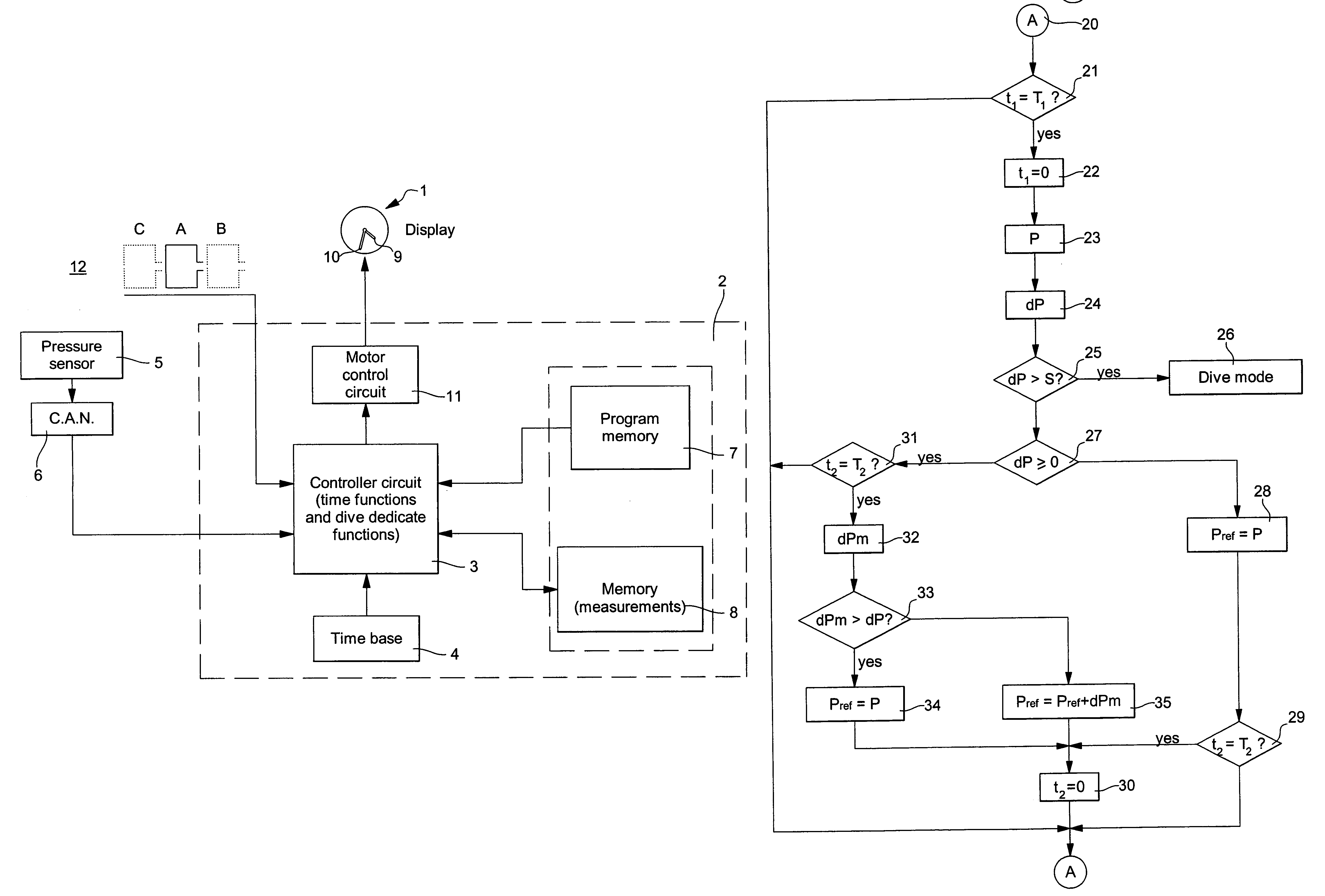
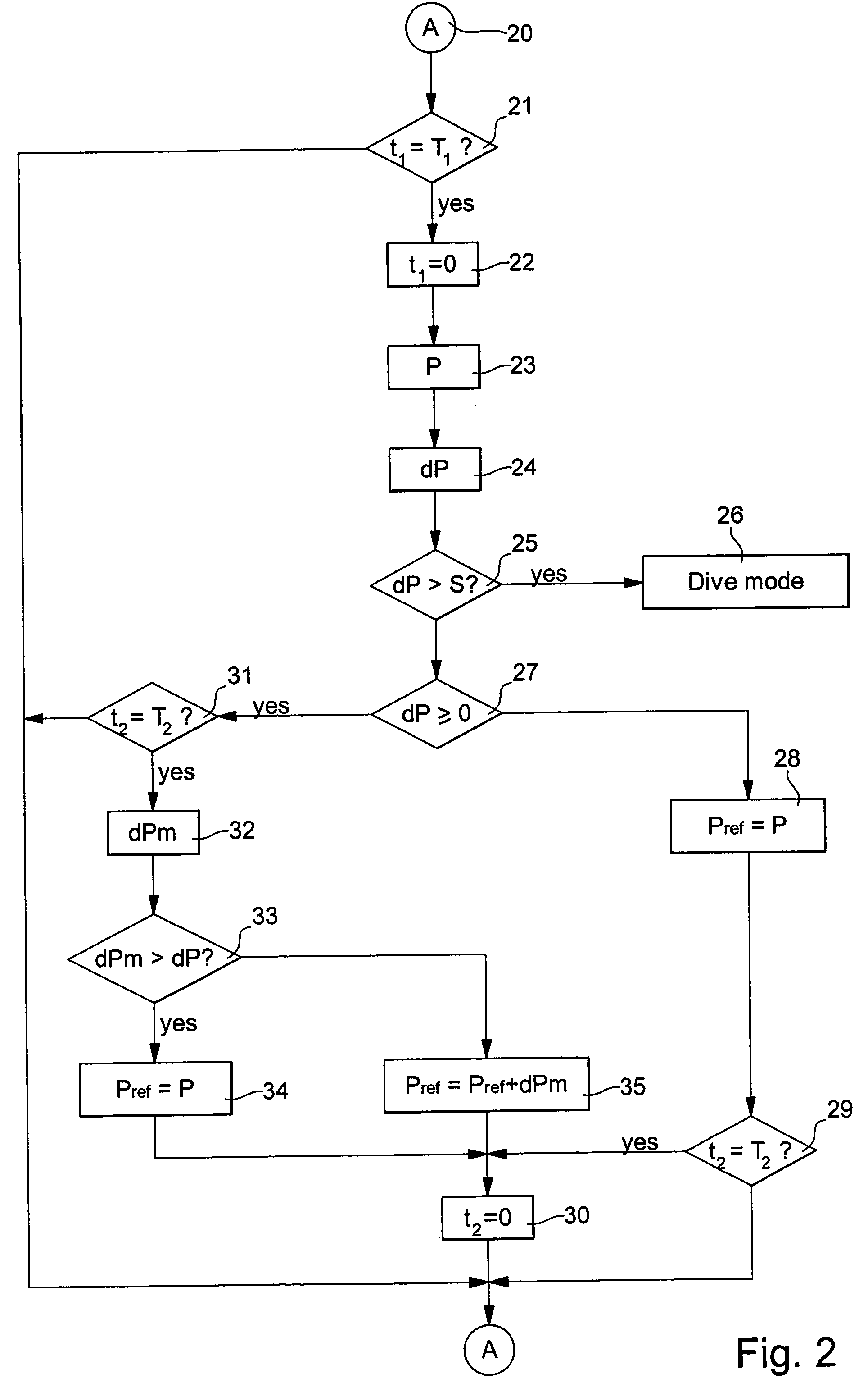
[0046]FIG. 2 shows a schematic diagram detailing the main steps of the dive start detection method according to the present invention.

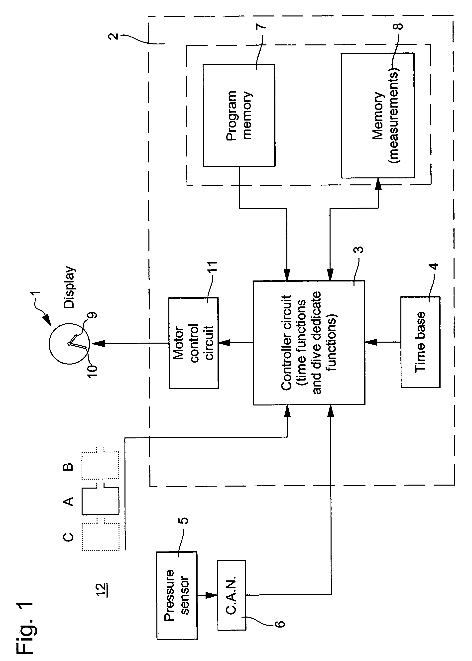
[0047]Controller circuit 3 is programmed to periodically power pressure sensor 5 when the watch is in time mode, to carry out ambient pressure value measurements.

[0048]The method starts at stage A, marked by the reference numeral 20, of the diagram, a previously measured pressure value being stored as the reference pressure Pref. Further, a first counter (not shown) is provided for measuring first time intervals t1, this counter having a value t1 comprised between 0 and T1 at stage A, T1 being a measurement period value. Preferably, period T1 is substantially comprised between 0.1 and 10 seconds.

[0049]At step 21 of the diagram, from stage A, controller circuit 3 tests the value of the first counter. While the counter value is not equal to T1, the method returns to step A, preferably, but not in a limitative manner, once per second, the counter value b...

second embodiment

[0072]FIG. 3 shows a schematic diagram detailing the main steps of the method for detecting the start of a dive according to the present invention.

[0073]As the first steps of the method according to this embodiment as far as comparison of the pressure variation value to the trigger threshold value S at 25, are the same as in the first embodiment, they will not be described in detail. Moreover, the reference numerals used within the scope of the first embodiment for these steps have been carried over to FIG. 3.

[0074]When the pressure variation value dP is less than trigger threshold S, which corresponds to an increase or stagnation in the pressure between the last time that reference pressure value Pref was stored and the last ambient pressure measurement P carried out, the controller circuit passes to an additional test at 40.

[0075]The additional test 40 consists in checking whether the value t2 of a second counter has reached the value T2 corresponding to the frequency f2 at which ...

third embodiment

[0088]FIG. 4 shows a schematic diagram detailing the main steps of the method for detecting the start of a dive according to the present invention.

[0089]As the first steps of the method according to the present embodiment as far as determination of the sign of the pressure variation, at step 27, are the same as in the first embodiment, they will not be described in detail. Moreover, the reference numerals used in the first embodiment for these steps have been carried over to FIG. 4.

[0090]The method according to this embodiment differs from the two preceding embodiments mainly by the nature of the quantity used for correcting the stored reference pressure value, which here is a predefined quantity and no longer a quantity based on measured ambient pressure values.

[0091]When the result of test 27 indicates that the value of dP is negative, which corresponds to a pressure decrease between the last stored reference pressure value Pref and the last ambient pressure measurement P carried ...


PUM

PropertyMeasurementUnit
frequencyaaaaaaaaaa
frequencyaaaaaaaaaa
frequencyaaaaaaaaaa

Abstract

The present invention concerns a method for detecting the start of a dive for implementation in a portable electronic device (1) of the diving computer type. More specifically, the method is for implementation in a device of this type having at least a first operating mode and a second operating mode, called the dive mode. This device includes a pressure sensor (5) for measuring the ambient pressure value (P) and electronic circuits (2) for processing the pressure measurement results including a time base (4) and at least one memory zone (7, 8).The detection method according to the present invention more particularly proposes making correction to certain measured pressure values before storing them as reference pressure values (Pref). Thus, the start of a dive can be detected with a high level of reliability solely on the basis of ambient pressure measurements.

Description

[0001]This application claims priority from European Patent Application No. EP 04101172.1 filed Mar. 22, 2004 the entire disclosure of which is incorporated herein by reference.FIELD OF THE INVENTION[0002]The present invention concerns a method for detecting the start of a dive for implementation in a portable electronic device of the diving computer type. More specifically, the method is for implementation in a device of this type having at least a first operating mode and a second operating mode, called the dive mode. This device includes, in particular, a pressure sensor for measuring the value of the ambient pressure and electronic circuits for processing the results of the pressure measurements including a time base and at least one memory zone.[0003]The detection method according to the present invention is based on the study of variations in the ambient pressure as a function of time in order to detect the start of a dive causing a significant increase in the value of the amb...

Claims


Application Information

Patent Timeline
Patent Type & Authority Patents(United States)
IPC IPC(8): A61M16/00A62B7/00B63C11/02G01L9/00G04G99/00B63C11/32G01C5/06G01C13/00G04B47/06G04C3/00G04G21/02
CPCB63C11/32G04G21/02G01C5/06B63C2011/021G01C25/00
Inventor CLAUDE, STEPHANECHRISTE, LAURENT
Owner ETA SA MFG HORLOGERE SUISSE
Why Eureka
Try Eureka