Interlabial pad
a technology of interlabial pads and pads, applied in the field of interlabial pads, can solve the problems of drop out of the wearer's labia, and deterioration of the inner wall, so as to prevent excessive irritation of the labia
- Summary
- Abstract
- Description
- Claims
- Application Information
AI Technical Summary
Benefits of technology
Problems solved by technology
Method used
Image
Examples
embodiment 1
Slit
Overall Configuration of Interlabial Pad
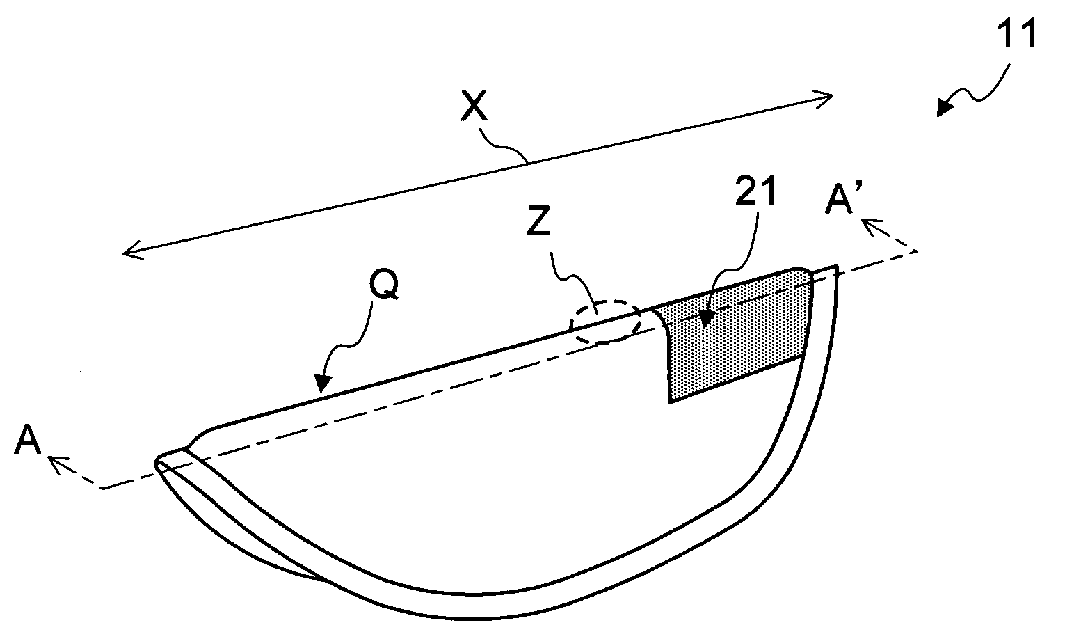
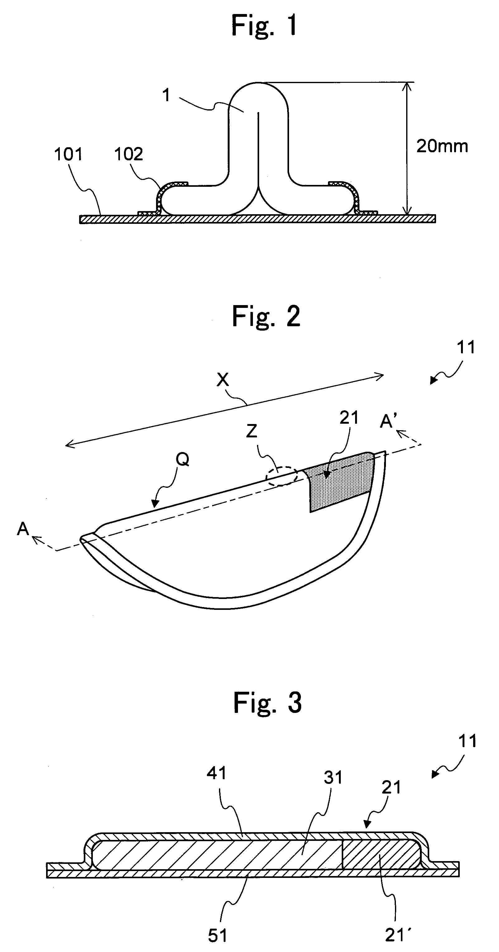
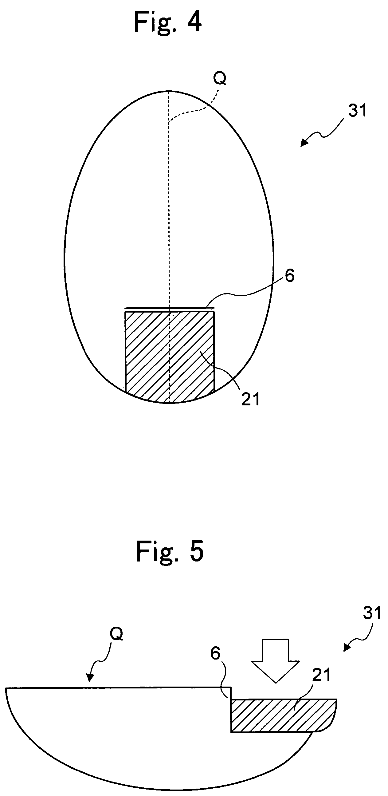
[0057]FIG. 2 is a perspective view of an interlabial pad 11 relating to Embodiment 1, folded in two. The interlabial pad 11 of the present embodiment has a central axis Q extending along a longitudinal direction X. The pad 11 is folded in two, with the central axis Q as a folding line, and is worn with at least one portion held between labia minora of the labia, so that at least one portion close to the central axis Q touches a vestibule floor inside the labia. In addition, the pad 11 is provided with a rear portion low compression rigidity structure, by which the rear portion that is positioned to the rear of a wearer, and that touches the body of the wearer first when worn, has low compression rigidity in comparison to a front portion positioned to the front, so that the rear portion of the pad has a low compression rigidity portion 21.
[0058]FIG. 3 is a cross-sectional view of FIG. 2 at A-A′. As shown in FIG. 3, the interlabial pad 11 of...
embodiment 2
Embossment
[0092]An interlabial pad relating to Embodiment 2 will now be explained. In Embodiment 2, as the “rear portion low compression rigidity structure”, an embossment 7 is provided with the absorbent body 32. In Embodiment 2, by providing an embossment 7, with the embossment area given high rigidity, as a trigger for the embossment area to bend, it is possible to arrange that the rear portion of the pad only compresses first.
Rear Portion Low Compression Rigidity Structure
[0093]FIG. 7 is a plan view of an absorbent body 32 of an interlabial pad related to Embodiment 2. In Embodiment 2, the embossment 7 is arranged in a discontinuous row in a direction perpendicular to the direction of the central axis Q. Furthermore, to explain the behavior of the embossment 7 in Embodiment 2, FIG. 8 is a side view with compression force applied in a vertical direction to the absorbent body 32 that is folded in two.
[0094]As shown in FIG. 7, the embossment 7 is implemented discontinuously in an a...
modified example of embodiment 2
[0098]FIG. 9 is a plan view of an absorbent body 33 of an interlabial pad related to a modified example of Embodiment 2. In the absorbent body 33 shown in FIG. 9, embossments 71 are disposed adjacently and discontinuously, at intervals, in an area extending more towards the front than the center point of the central axis Q. In the pad using this type of absorbent body 33, the rigidity of the low compression rigidity portion 23, the portion that makes contact more to the rear than the posterior labial commissure when worn, is lower than the rigidity of the portion that fits the vestibule floor so that the rear portion of the pad is compressed easily, and can bend easily in a direction away from the body, first.
PUM
 Abstract
Description
Claims
Application Information
 - R&D
- Intellectual Property
- Life Sciences
- Materials
- Tech Scout
- Unparalleled Data Quality
- Higher Quality Content
- 60% Fewer Hallucinations
Browse by: Latest US Patents, China's latest patents, Technical Efficacy Thesaurus, Application Domain, Technology Topic, Popular Technical Reports.
© 2025 PatSnap. All rights reserved.Legal|Privacy policy|Modern Slavery Act Transparency Statement|Sitemap|About US| Contact US: help@patsnap.com


