
Lever-type connector and lever-type connector assembly

a technology of lever-type connectors and lever-type connectors, which is applied in the direction of coupling device connection, engagement/disengagement of coupling parts, contact surface shape/structure, etc., can solve the problems of deterioration of lever operation, and achieve significant labor and time savings, convenient disassembly, and miniaturization of connectors

Inactive Publication Date: 2008-11-04
SUMITOMO WIRING SYST LTD
View PDF11 Cites 14 Cited by
  • Summary
  • Abstract
  • Description
  • Claims
  • Application Information

AI Technical Summary

Benefits of technology

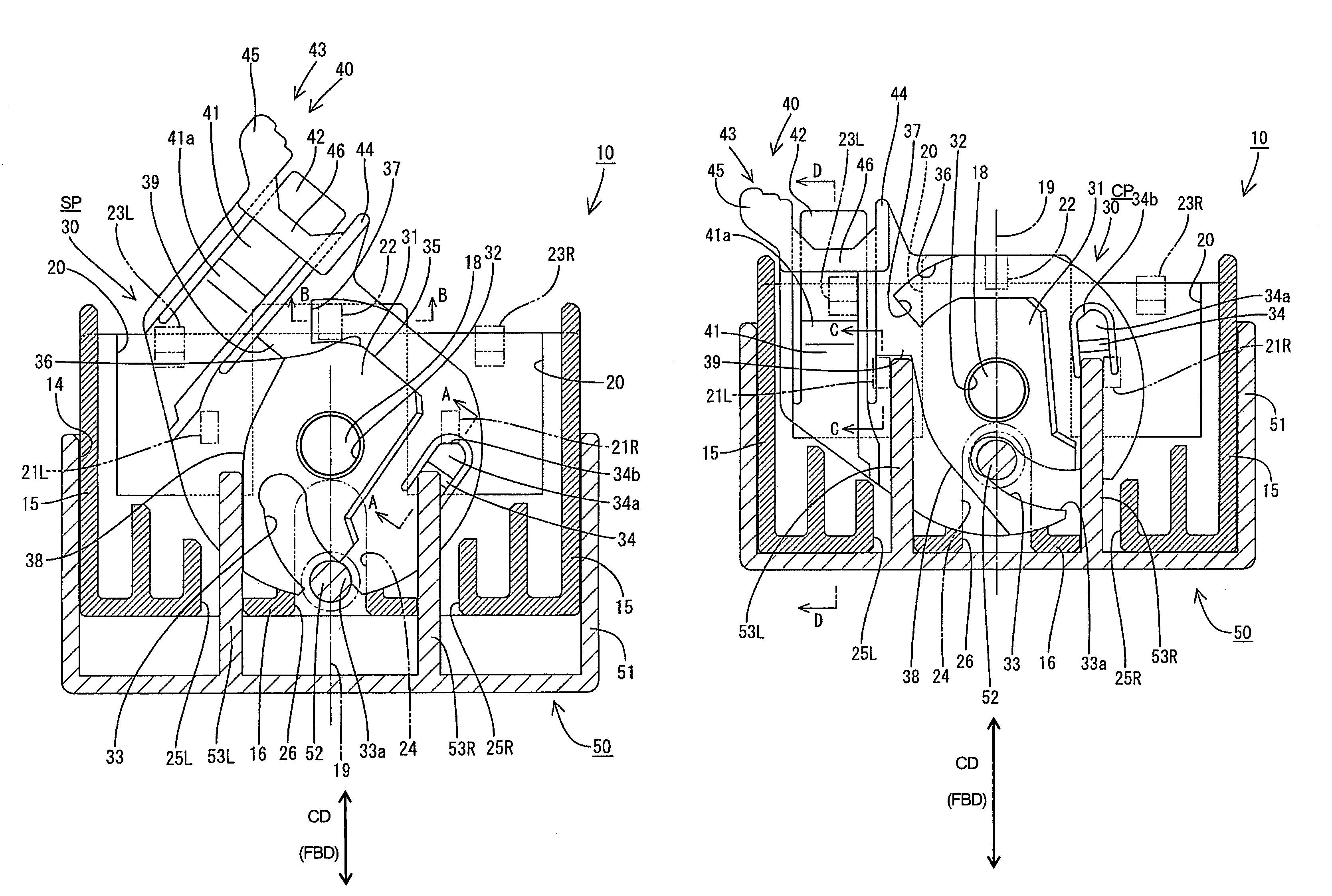
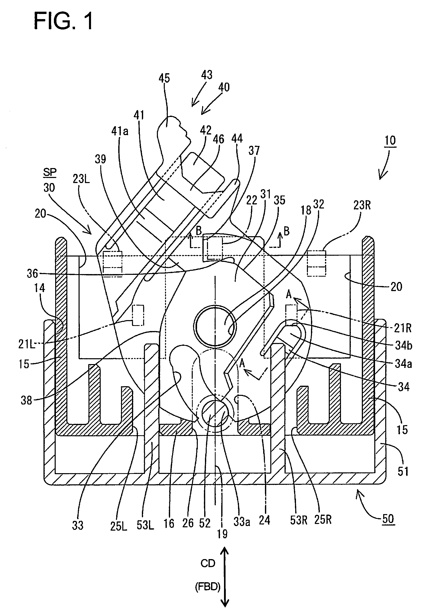
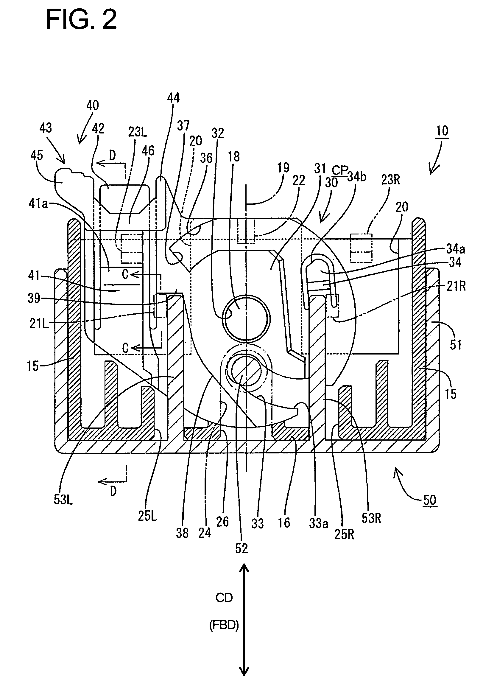
[0008]The lever can be assembled with the first housing in either of the two postures substantially symmetrical with respect to the axis of symmetry, and the displacement direction of the lever changes depending on the assembling posture. Accordingly, the displacement operability of the lever can be improved by selecting the assembling posture of the lever depending on circumstances in which the connector is arranged. Further, the plate-shaped lever is smaller than a lever that has an operable portion and arms at opposite ends of the operable portion. The holding means can hold the lever at the standby position regardless of the posture in which the lever is assembled, and the lever can be locked at the connection position by the locking means.
[0017]The lever preferably is supported detachably on the first housing in either of the two postures and can be detached by being displaced away from the first housing after moving from the connection position to a detachment position. Accordingly, the connector can be miniaturized, and the lever can be detached conveniently with significant labor and time savings. Furthermore, it is not necessary to provide the lever for each connector by using the lever as a jig for connectors and hence the number of parts can be reduced.

Problems solved by technology

Thus, the operability of the lever may be deteriorated if the connector is arranged in a narrow space.

Method used


Image

  • Lever-type connector and lever-type connector assembly
  • Lever-type connector and lever-type connector assembly
  • Lever-type connector and lever-type connector assembly

Examples


first embodiment

[0054]the present invention is described herein with reference to FIGS. 1 to 16. A connector according to this embodiment has a first housing 10 and a second housing 20 that are connected with and separated from each other using a movable member a lever 30. In the following, sides of the housings 10, 20 to be connected with each other are referred to as front.

[0055]The first housing 10 is made e.g. of a synthetic resin and is substantially in the form of a rectangular block. The first housing 10 includes a wide substantially block-shaped terminal accommodating portion 11 and cavities 12 penetrate the terminal accommodating portion 11 in forward and backward directions FBD. A terminal fitting (not shown) is inserted into each cavity 12 from behind and is locked by a lock 13 formed in the cavity 12. A wire (not shown) is connected with the rear end of the terminal fitting and is drawn out backward from the first housing 10.

[0056]A rearwardly open accommodation space 14 is provided on ...

second embodiment

[0117]The detaching portions are arranged substantially transversely symmetrical with respect to the axis of symmetry in the However, they may be substantially on the axis of symmetry.


PUM


Abstract

A lever (30) can be assembled in either of two postures symmetrical with respect to an axis of symmetry (19), and the rotating direction of the lever (30) changes depending on the assembling posture. Thus, the rotating direction of the lever (30) can be selected depending on circumstances. A cam follower (52) can enter a cam groove (33) regardless of the posture in which the lever (30) is assembled. The lever (30) can be held at a standby position by a holder (21L, 21R, 22, 34, 36), and the lever (30) can be locked at a connection position by a lock (21L, 21R, 23L, 23R, 39, 41).

Description

BACKGROUND OF THE INVENTION[0001]1. Field of the Invention[0002]The invention relates to a lever-type connector.[0003]2. Description of the Related Art[0004]U.S. Pat. No. 5,611,703 discloses a connector with a lever that is assembled rotatably with a first housing. The lever has a cam groove that receives a cam follower of a second housing when the lever is at a standby position. The lever then is displaced to a connection position. As a result, the cam groove engages the cam follower and develops a force multiplying action that connects the two housings.[0005]The lever has an operable portion and two plate-shaped arms that extend from the opposite ends of an operable portion. The arms are present at the opposite sides of the first housing, and hence enlarge the connector. The lever is assembled with the first housing in only one mode, and the operating direction of the lever is restricted. Thus, the operability of the lever may be deteriorated if the connector is arranged in a narr...

Claims


Application Information

Patent Timeline
Patent Type & Authority Patents(United States)
IPC IPC(8): H01R13/66
CPCH01R13/62938H01R13/6295H01R13/62955
Inventor SAKATANI, ATSUSHIUCHIYAMA, YOSHIHIROSAKURAI, TOSHIKAZU
Owner SUMITOMO WIRING SYST LTD
Learn More