Eureka AIR delivers breakthrough ideas for toughest innovation challenges, trusted by R&D personnel around the world.

Retaining device for a linear transmission system

a technology of retaining device and linear transmission system, which is applied in the direction of linear bearings, shafts and bearings, bearings, etc., can solve the problems of falling off of rolling elements, affecting and the conventional retaining device b>10/b> cannot perfectly mate with the sliding block, etc., to achieve the effect of simplifying the assembly and disassembly process of rail clamps

Active Publication Date: 2008-11-04
HIWIN TECH
View PDF4 Cites 3 Cited by
  • Summary
  • Abstract
  • Description
  • Claims
  • Application Information

AI Technical Summary

Benefits of technology

[0012]The primary objective of the present invention is to simplify the assembly and disassembly process of the rail clamp. The present invention comprises: a sliding block, a rail clamp and a spring fastener. The sliding block includes an upper retainer formed with a positioning hole. The rail clamp includes two retaining members and two elastic members. When assembling the rail clamp into the sliding block, the two elastic members between the rail clamp are compressed and inserted into the sliding block, and ten the rail clamp is positioned in the sliding block by the spring fastener. And when disassembling the rail clamp, the user only needs to push the rail clamp slightly, the spring fastener will be disengaged form the sliding block, and the rail clamp can be removed from the sliding block.

Problems solved by technology

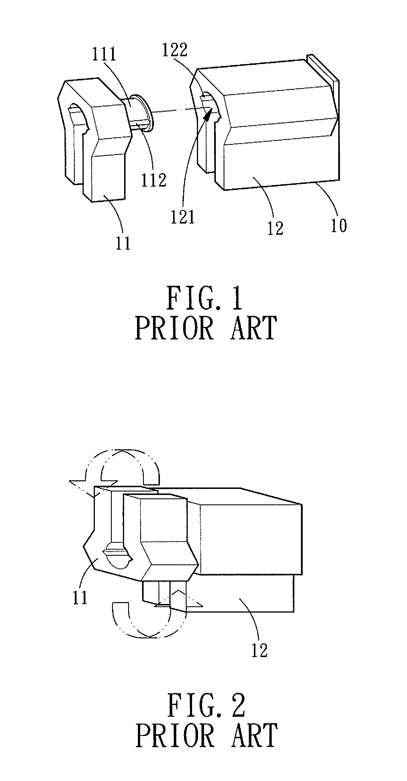
However, the conventional rail clamp itself cannot be fixed on the sliding block, plus the rolling elements are very sensitive, the rail clamp will disengage from the sliding block as long as it is tilted a bit, causing the fall-off of the rolling elements.
Furthermore, the conventional retaining device 10 cannot perfectly mate with the sliding block, and it will get a little loose even when both rotary blocks 11 are fixed.

Method used


Image

  • Retaining device for a linear transmission system
  • Retaining device for a linear transmission system
  • Retaining device for a linear transmission system

Examples


Embodiment Construction

[0023]The present invention will be more clear from the following description when viewed together with the accompanying drawings, which show, for purpose of illustrations only, the preferred embodiment in accordance with the present invention.

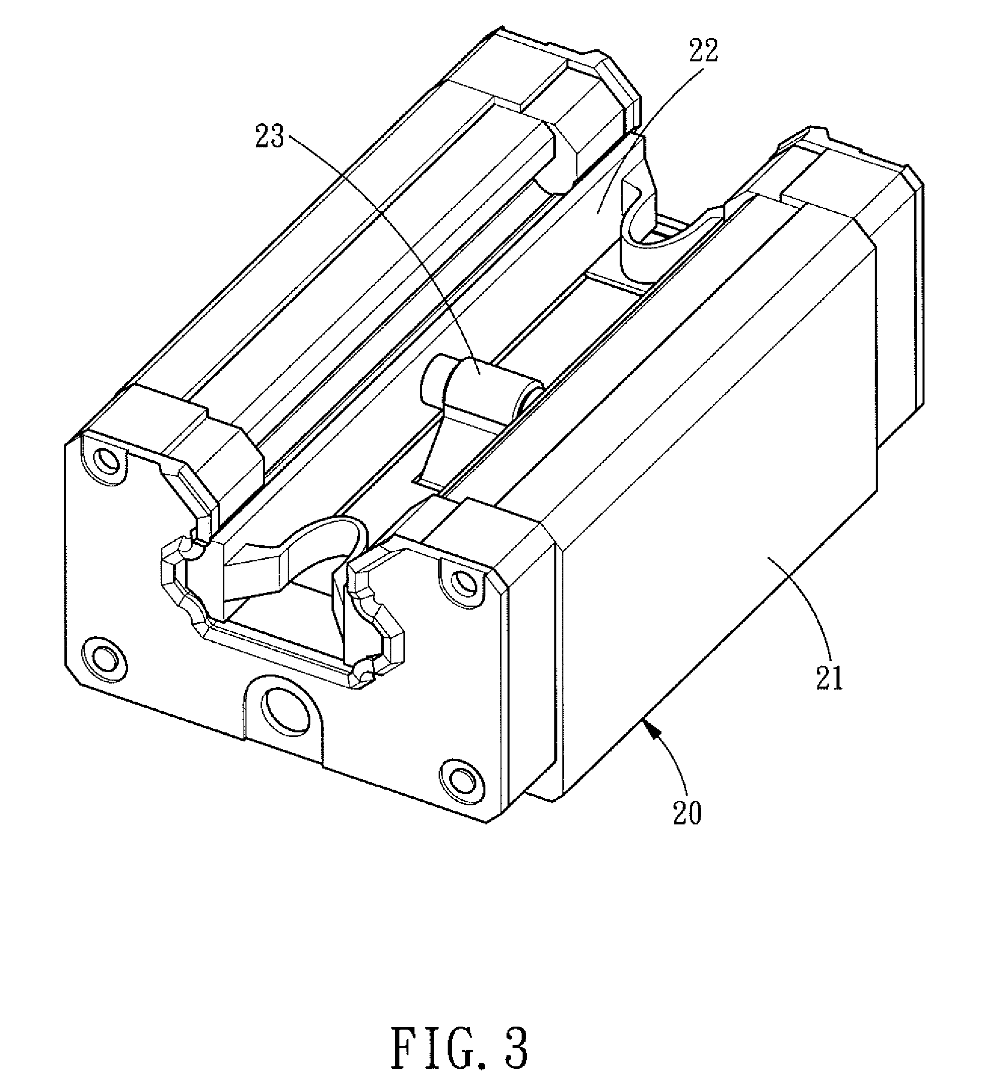
[0024]Referring to FIGS. 3 and 4, a retaining device 20 for a linear transmission system comprises: a sliding block 21, a rail clamp 22, and a spring fastener 23.

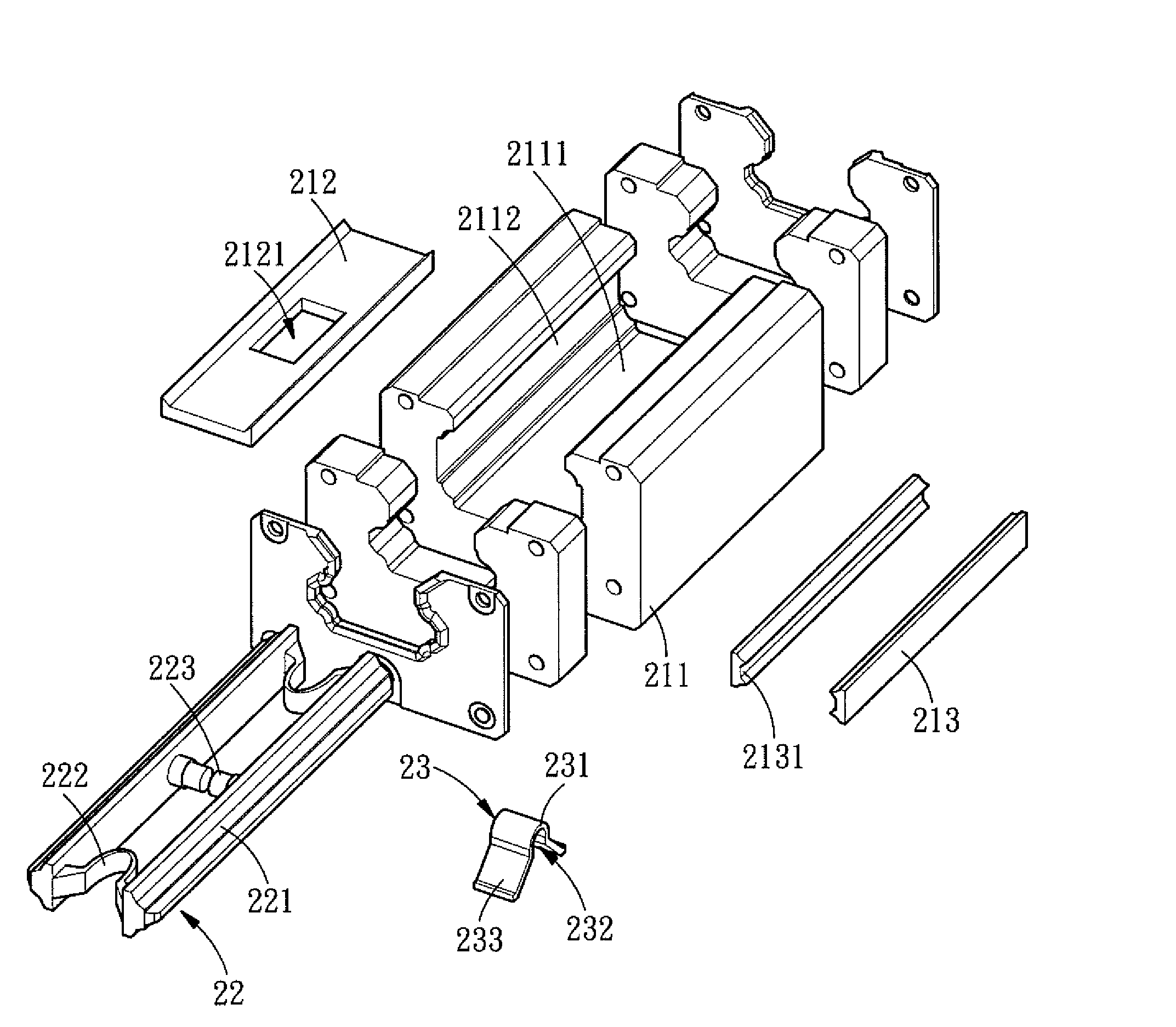
[0025]The sliding block 21 includes a base 211, an upper retainer 212, two mid retainers 213, two lower retainers 214, and a plurality of rolling elements 215. The base 211 is a U-shaped structure in cross section and has an upper connecting surface 2111, two mid connecting surfaces 2112, and two lower connecting surfaces 2113. The upper retainer 212 is disposed on the upper connecting surface 2111 of the base 211, and a rectangular positioning hole 2121 is formed in the upper retainer 212. The two mid retainers 213 are disposed on the two mid connecting surfaces 2112 of the base 211,...


PUM


Abstract

A retaining device for a linear transmission system comprises: a sliding block, a rail clamp and a spring fastener The sliding block includes an upper retainer formed with a positioning hole. The rail clamp includes two retaining members and two elastic members, and the two retaining members are symmetrically arranged and are connected by the two elastic members. The two elastic members can adjust the interval between the two retaining members. The spring fastener is pivotally arranged between the two retaining members of the rail clamp and is provided with two elastic retaining portions to be engaged in the positioning hole of the upper retainer. After the rail clamp is installed in the sliding block, the two elastic members of the spring fastener will be engaged in the positioning hole, thus fixing the rail clamp in the sliding block.

Description

BACKGROUND OF THE INVENTION[0001]1. Field of the Invention[0002]The present invention relates to a linear transmission system, and more particularly to a retaining device for a linear transmission system. The rail clamp can be closely installed in the sliding block, the spring fastener enables the rail clamp to be positioned in the sliding block very quickly, and the rail clamp can be disassembled easily with a small force, thus improving the positioning effect of the rail clamp while reducing the assembling and disassembling time.[0003]2. Description of the Prior Art[0004]Sliding block is installed on the rail, and a plurality of rolling elements is provided in the sliding block for enabling the sliding block to slide relative to the rail. When the sliding block is separated from the rail, the rolling elements will also fall off the sliding block. At this moment, rail clamp is used in assembly of the sliding block to prevent the rolling elements from falling off the sliding block. ...

Claims


Application Information

Patent Timeline
Patent Type & Authority Patents(United States)
IPC IPC(8): F16C29/06
CPCF16C29/0647F16C41/045
Inventor CHEN, HSING-LIANG
Owner HIWIN TECH
Why Eureka
Eureka Blog
Learn More