
Communication device for a movable body

a communication device and movable body technology, applied in the direction of process and machine control, instruments, gymnastics, etc., can solve the problems of reducing communication efficiency, taking a long time to converge the route, and becoming difficult to communicate between vehicles behind obstacles

Inactive Publication Date: 2008-10-28
AISIN SEIKI KK
View PDF20 Cites 31 Cited by
  • Summary
  • Abstract
  • Description
  • Claims
  • Application Information

AI Technical Summary

Benefits of technology

The present invention is about a communication device for a movable body that can exchange information with other movable bodies. The device has a surrounding detecting system to find out the surrounding of the movable body, a determining system to determine if a relay is needed to transmit the information, and a transmitting and receiving system to send and receive the information. The technical effect of this invention is to improve the efficiency and accuracy of information exchange among movable bodies.

Problems solved by technology

However, because the wireless communication generally uses signals of a high frequency wave, when obstacles such as a building exist between the vehicles, it becomes difficult to communicate between vehicles behind the obstacles.
However, within the Multi-hop Wireless Network between movable bodies such as vehicles, because the signals are randomly hopped, it takes some time to converge the route and communication efficiency is decreased

Method used


Image

  • Communication device for a movable body
  • Communication device for a movable body
  • Communication device for a movable body

Examples


Embodiment Construction

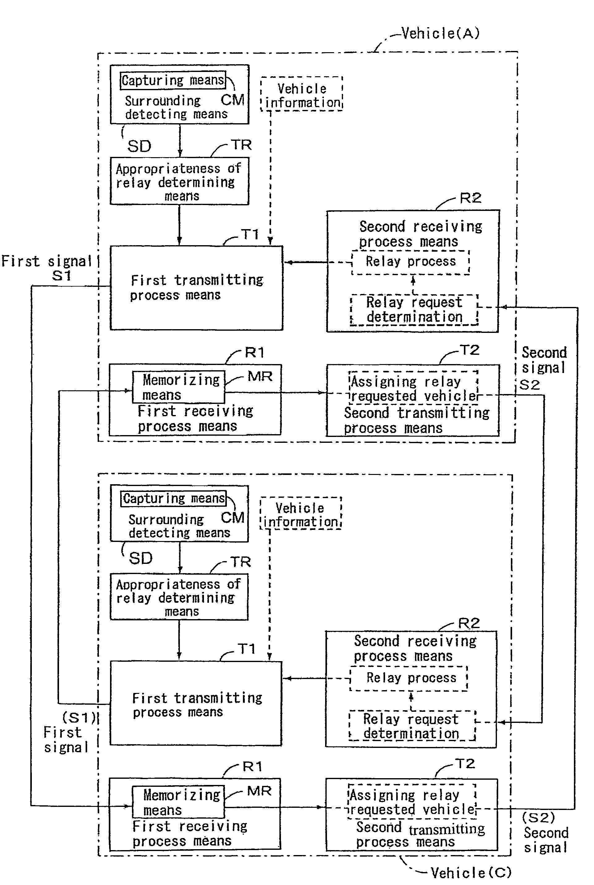
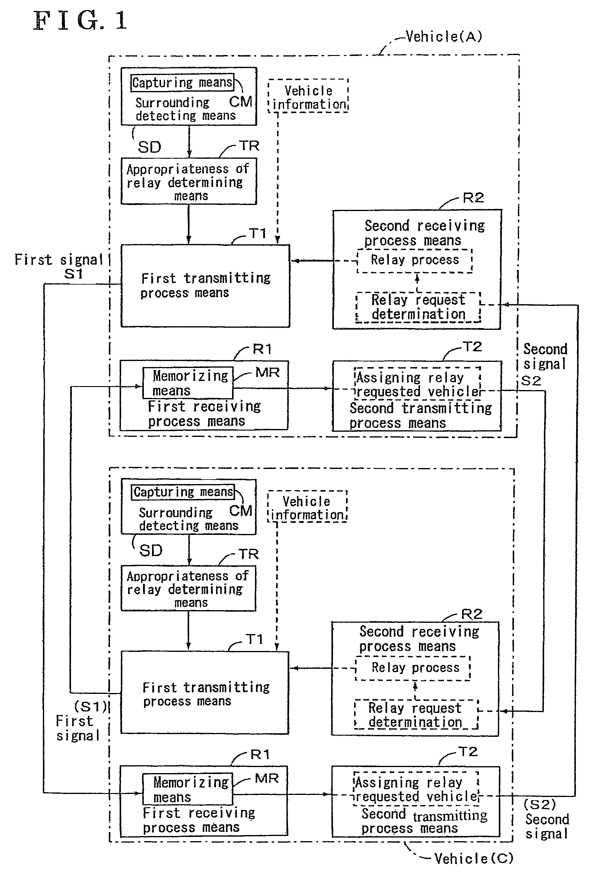
[0019]An embodiment of the communication device for a movable body according to the present invention will be explained in accordance with the attached drawings. As shown in FIG. 1, the communication device for a movable body is mounted to each of the vehicles, for example to a vehicle A and a vehicle C illustrated with a chain line, and they communicate each other as described later. Specifically, each of the vehicles A and C includes a surrounding detecting means SD, an appropriateness of relay determining means TR, a first transmitting process means T1, a first receiving process means R1, a second transmitting process means T2 and a second receiving process means R2. More specifically, the surrounding detecting means SD detects a surrounding of the vehicle, and the appropriateness of relay determining means TR determines whether or not the relay is appropriate on the basis of the detected result by the surrounding detecting means SD. Further, according to the vehicle A, the first...


PUM


Abstract

A communication device for a movable body mounted to each of movable bodies for exchanging information among the movable bodies includes a surrounding detecting device for detecting a surrounding of the movable body, an appropriateness of relay determining device for determining an appropriateness of relay, a first transmitting process device for transmitting a first signal, a first receiving process device for receiving the first signal sent by the first transmitting process device, a second transmitting process device for determining whether or not the relay is required, and a second receiving process device for receiving the second signal sent by the second transmitting process device.

Description

CROSS REFERENCE TO RELATED APPLICATIONS[0001]This application is based on and claims priority under 35 U.S.C. § 119 to Japanese Patent Application 2005-038692, filed on Feb. 16, 2005, the entire content of which is incorporated herein by reference.FIELD OF THE INVENTION[0002]The present invention generally relates to a communication device, which is mounted to each of the movable bodies, in order to exchange information among the movable bodies.BACKGROUND[0003]Various types of communicating device for transmitting and receiving signals among plural vehicles in order to exchange information have been known so far, and, for example, an inter-vehicle communication system disclosed in JP2001-283381A is capable of communicating information among plural vehicles traveling on a road. The inter-vehicle communication system includes a drive aiding camera mounted on the user's vehicle itself in order to support driving and captures images around the user's vehicle. On the basis of the capture...

Claims


Application Information

Patent Timeline
Patent Type & Authority Patents(United States)
IPC IPC(8): G08G1/16G08G1/00
CPCB60W40/04G08G1/163G08G1/0967G08G1/096791A63B19/02A61H39/04
Inventor KONISHI, YOSHICHIKAYAMAMOTO, YASUMASANIWA, EIJI
Owner AISIN SEIKI KK
Learn More