
Swelling element packer and installation method

a technology of swelling elements and packers, which is applied in the directions of packaging, sealing, borehole/well accessories, etc., can solve the problems of limited design and no solution offered

Active Publication Date: 2008-10-28
BAKER HUGHES INC
View PDF35 Cites 109 Cited by
  • Summary
  • Abstract
  • Description
  • Claims
  • Application Information

AI Technical Summary

Problems solved by technology

These designs were still limited to the amount of swelling from the sealing element as far as the developed contact pressure against the surrounding tubular or wellbore.
In some designs there were also issues of extrusion of the sealing element in a longitudinal direction as it swelled radially but no solutions were offered.

Method used


Image

  • Swelling element packer and installation method
  • Swelling element packer and installation method
  • Swelling element packer and installation method

Examples


Embodiment Construction

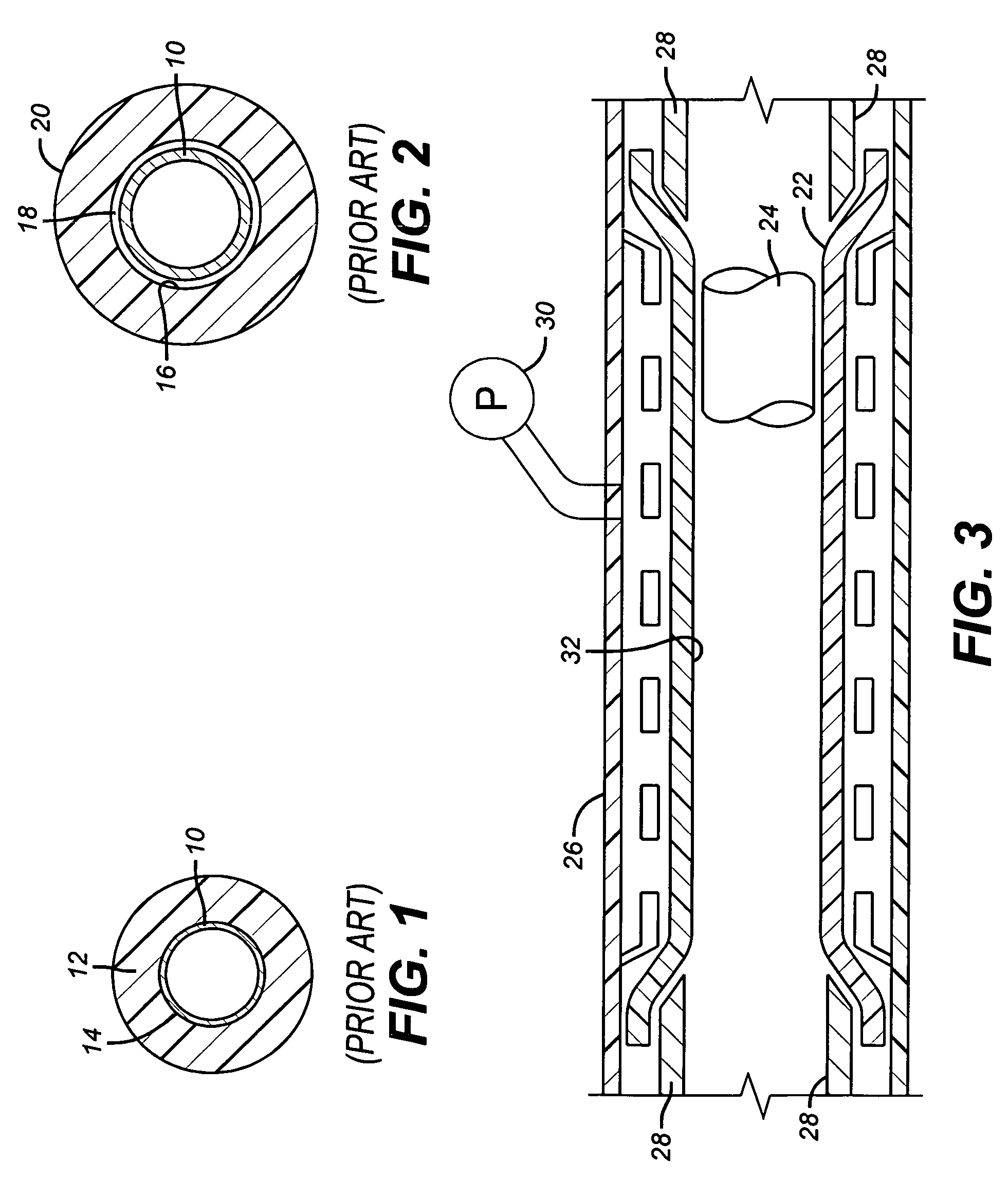
[0066]FIG. 3 is a schematic drawing of one way to get a swelling element 22 mounted on a mandrel 24 by securing it to slotted tube 26 and using retaining wedges 28 to seal off the ends. A vacuum source 30 is applied to the outside of the slotted tube 26 which reduces the inside diameter 32 of the element 22. With the vacuum applied the inside diameter 32 is larger than the outside diameter of the mandrel 24 to allow the mandrel 24 to be moved through the inside diameter 32. When the relative position between the element 22 and the mandrel 24 is achieved, the vacuum is removed and the inside diameter 32 grows until it makes intimate contact with the mandrel 24. The initial inside diameter 32 before a vacuum is pulled is preferably smaller than the outside diameter of the mandrel 24. After the vacuum is removed, the retaining wedges 28 can be removed and what is left is an element 22 that is stretched over the mandrel 24 leaving residual circumferential tensile forces in the element 2...


PUM


Abstract

A sealing element that swells on exposure to well fluids present or added to the wellbore is assembled to the mandrel in a manner to induce circumferential stresses proximately to the inside diameter of the element so as to resist the tendency of the inside diameter of the element to grow during the swelling process. A vacuum and a pressure method are described. Leak paths between the mandrel and the sealing element are minimized or eliminated as a result.

Description

FIELD OF THE INVENTION[0001]The field of this invention is packers whose elements swell downhole to create a seal and methods for installation of the swelling sealing element on the mandrel.BACKGROUND OF THE INVENTION[0002]Packers are used downhole to isolate portions of a wellbore from each other. There are many styles of packers. Some set by longitudinal compression of the sealing element by fluid pressure applied to a setting tool or by mechanical force such as from setting down weight. Other designs involve elements that are inflated. More recently, elements that swell to a sealing position on exposure to well fluids have been used. There have been many variations as outlined below.[0003]Packers have been used that employ elements that respond to the surrounding well fluids and swell to form a seal. Many different materials have been disclosed as capable of having this feature and some designs have gone further to prevent swelling until the packer is close to the position where ...

Claims


Application Information

Patent Timeline
Patent Type & Authority Patents(United States)
IPC IPC(8): E21B33/12
CPCE21B33/1208Y10S277/934E21B33/12
Inventor WOOD, EDWARD T.BAILEY, STEVEN N.LAFLIN, WALTER J.BERZIN, VELKORTE, JAMES R.O'MALLEY, EDWARD J.RICHARD, BENNETT M.
Owner BAKER HUGHES INC
Learn More