Eureka AIR delivers breakthrough ideas for toughest innovation challenges, trusted by R&D personnel around the world.

Amplitude demodulator for an electromagnetic transponder

a technology of electromagnetic transponders and demodulators, which is applied in the direction of amplitude-modulated carrier systems, amplitude-modulated subscriber stations, and indirect connection of subscriber stations, etc., which can solve the problem that the transponder is limited in practice to rates of 100 to 400 kbits/s

Active Publication Date: 2008-10-21
STMICROELECTRONICS SRL
View PDF4 Cites 8 Cited by
  • Summary
  • Abstract
  • Description
  • Claims
  • Application Information

AI Technical Summary

Problems solved by technology

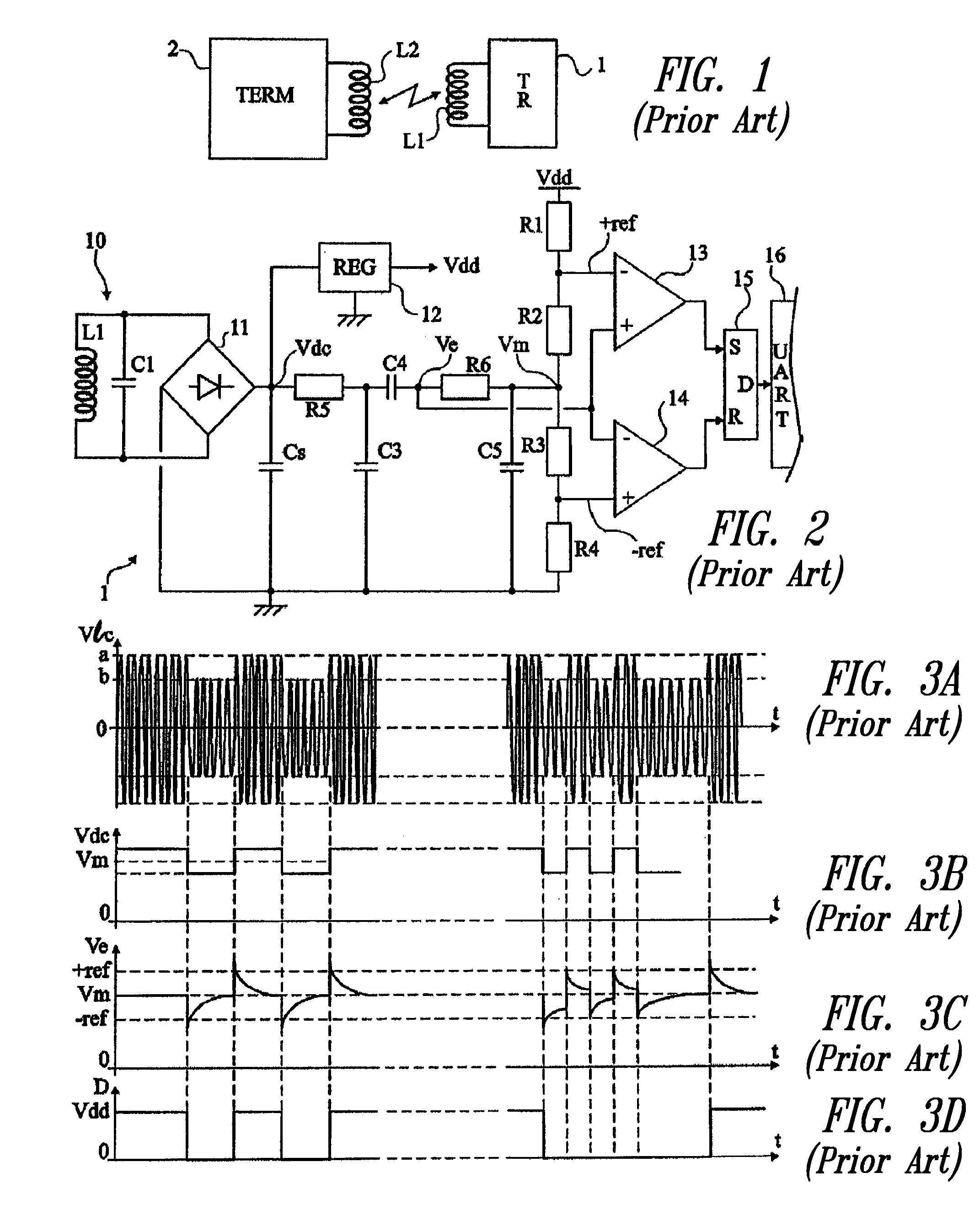
A problem is posed if the amplitude-modulation transmission flow rate is desired to be increased in the terminal-to-transponder direction.
This disadvantage results in that transponders are, in practice, limited to rates of from 100 to 400 kbits / s.
Reducing the detection window set by thresholds −ref and +ref is no solution to this problem since the demodulator would become too sensitive to noise.

Method used


Image

  • Amplitude demodulator for an electromagnetic transponder
  • Amplitude demodulator for an electromagnetic transponder
  • Amplitude demodulator for an electromagnetic transponder

Examples


Embodiment Construction

[0044]In the following description, certain specific details are set forth in order to provide a thorough understanding of various embodiments. However, one skilled in the art will understand that the present systems and methods may be practiced without these details. In other instances, well-known structures, protocols, and other details have not been shown or described in detail to avoid unnecessarily obscuring descriptions of the embodiments.

[0045]Reference throughout this specification to “one embodiment” or “an embodiment” means that a particular feature, structure or characteristic described in connection with the embodiment is included in at least one embodiment. Thus, the appearances of the phrases “in one embodiment” or “in an embodiment” in various places throughout this specification are not necessarily all referring to the same embodiment. Further more, the particular features, structures, or characteristics may be combined in any suitable manner in one or more embodimen...


PUM


Abstract

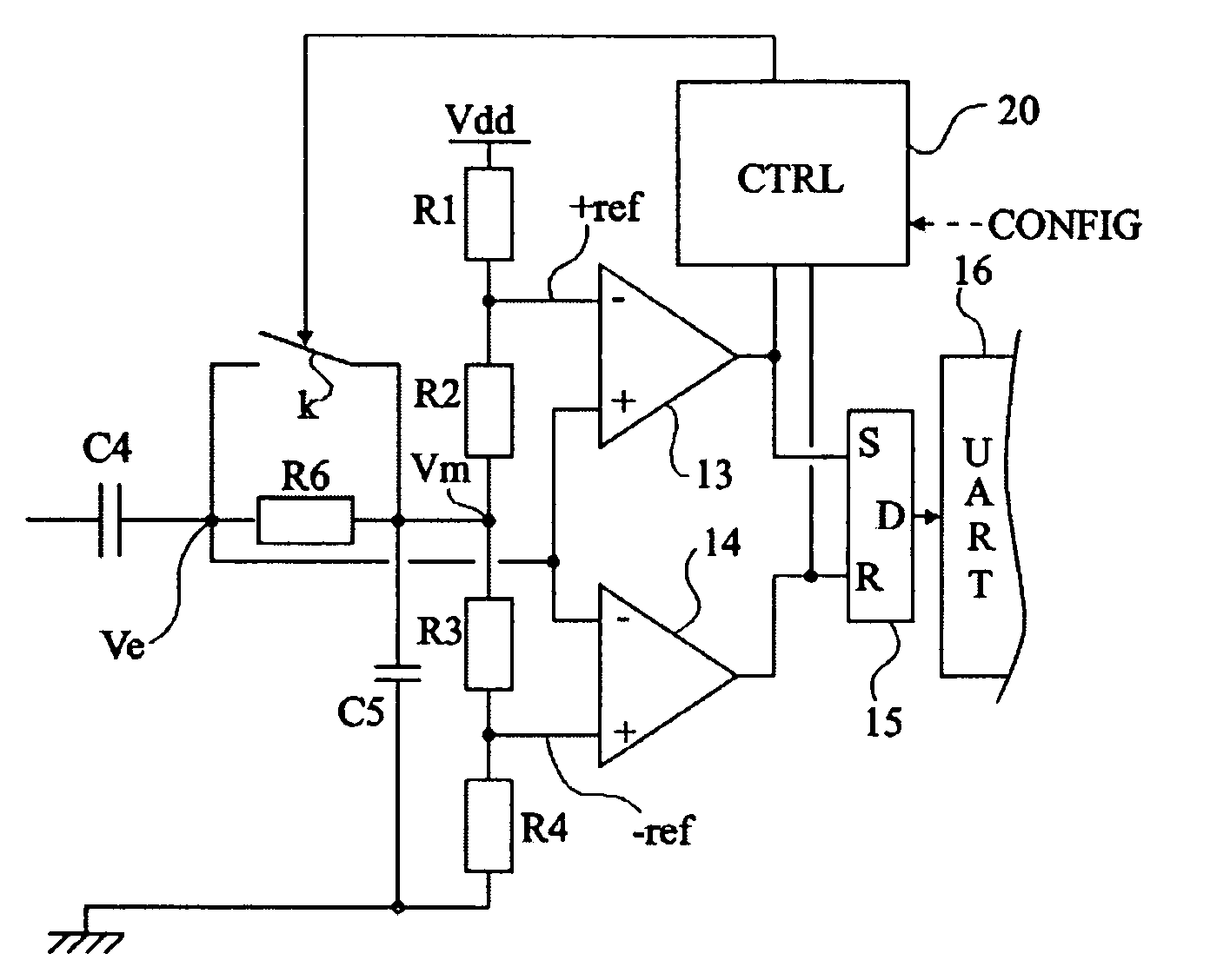
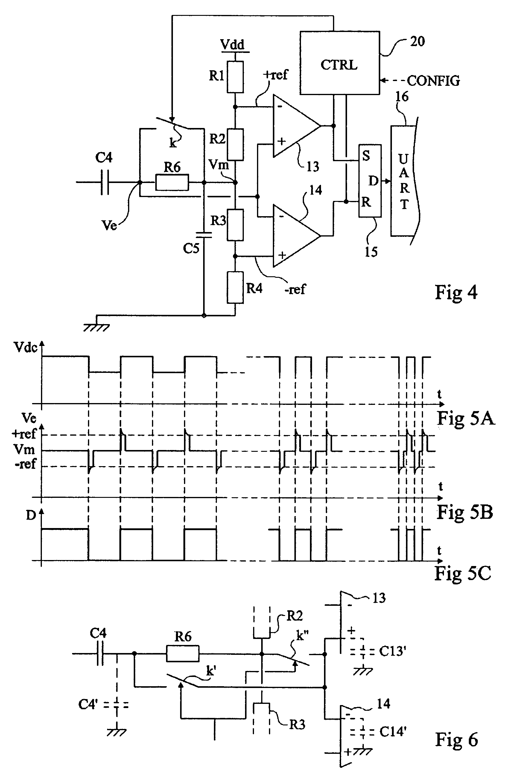
An amplitude demodulator comprising a capacitive element for filtering a first D.C. component of a received signal, an element for detecting edges in the signal provided by the capacitive element, and at least one switching element for forcing, at least after detection of an edge, the returning of the signal provided by the capacitive element to a second D.C. component.

Description

BACKGROUND OF THE INVENTION[0001]1. Field of the Invention[0002]The present invention generally relates to amplitude-modulation radio-frequency transmissions and, more specifically but not exclusively, to transmissions performed with a modulation index smaller than one.[0003]The present invention applies for example to electromagnetic transponder systems in which a high-frequency carrier is amplitude-modulated by a terminal for transmission to an electromagnetic transponder, for example, carried by an electronic tag or a smart card, in the field of the terminal. The present invention applies, as one possible example, to electromagnetic transponders in an electronic passport application.[0004]2. Discussion of the Related Art[0005]Systems for electromagnetic transponders are based on the cooperation between an oscillating circuit on the read / write terminal side and a resonant circuit on the electromagnetic transponder side (generally, a portable element), to exchange information by us...

Claims


Application Information

Patent Timeline
Patent Type & Authority Patents(United States)
IPC IPC(8): H03D1/10
CPCG06K19/0723H04L27/08
Inventor CONRAUX, JEROME
Owner STMICROELECTRONICS SRL
Why Eureka
Eureka Blog
Learn More