
Systems and methods for detecting contaminants

a technology of systems and methods, applied in the field of systems and methods for detecting contaminants, can solve the problems of imposing limits on the detection limit of the approach, affecting the detection effect, so as to facilitate the reduction or elimination of drawbacks

Active Publication Date: 2008-10-07
ENTEGRIS INC
View PDF13 Cites 16 Cited by
  • Summary
  • Abstract
  • Description
  • Claims
  • Application Information

AI Technical Summary

Benefits of technology

[0005]The present invention relates generally to systems and methods for obtaining a sample from a gas to measure one or more contaminants therein. In various embodiments, the present invention provides systems and methods for air sampling that facilitate reducing or eliminating the drawbacks associated with traditional wet impinger approaches to sampling.
[0006]In one aspect, the present invention provides a sampler where the collection material is a dry media. Accordingly, such dry samplers are liquid free avoiding the problems associated with liquid spillage and liquid evaporation inherent to wet impingers.
[0010]In various embodiments, the present invention provides a dry sampler having one or more of a low ammonia background and detection limit of 0.1 ppbV for a four hour sampling time that corresponds to a 240 L collected volume; a low pressure drop across the dry sampler to enable, for example, use of current hand-held pumps for active sampling system configurations; high capture efficiency for ammonia.

Problems solved by technology

Since continuous and semi-continuous sampling systems produce results on site, they are often large, complex and expensive to acquire, operate and maintain.
These wet impinging approaches have certain drawbacks including accidental spillage of the scrubbing media (typically, deionized (DI) water or a DI water solution), accidental inversions of the impinger, and limits to sampling time (thereby imposing limits on the lower-detection-limit of the approach) due to natural evaporation of scrubbing media (DI water).
In addition, wet impinger systems frequently require installation of the impinger by a highly trained technician.
Furthermore, wet impinger systems can be prone to bacterial contamination of the liquid scrubbing media and wet impinger vials are often made of fragile glass or quartz making them prone to breakage during shipment.

Method used


Image

  • Systems and methods for detecting contaminants
  • Systems and methods for detecting contaminants
  • Systems and methods for detecting contaminants

Examples


Embodiment Construction

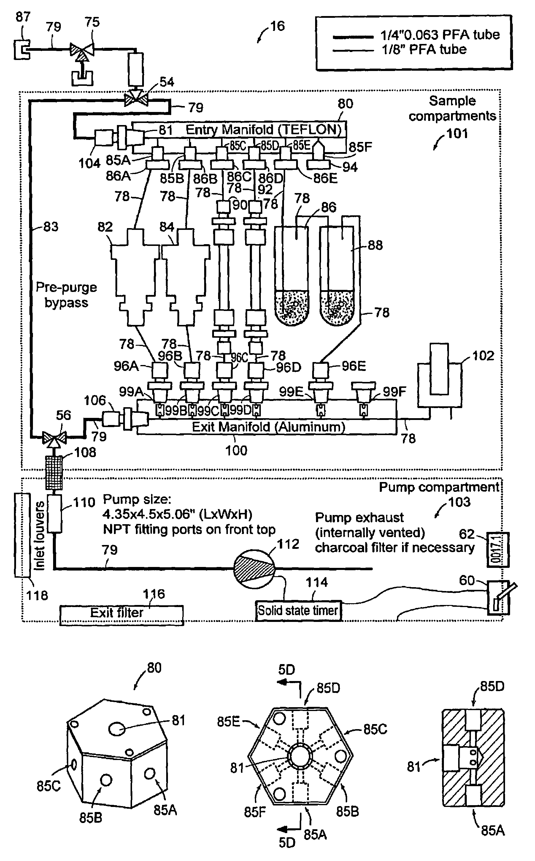
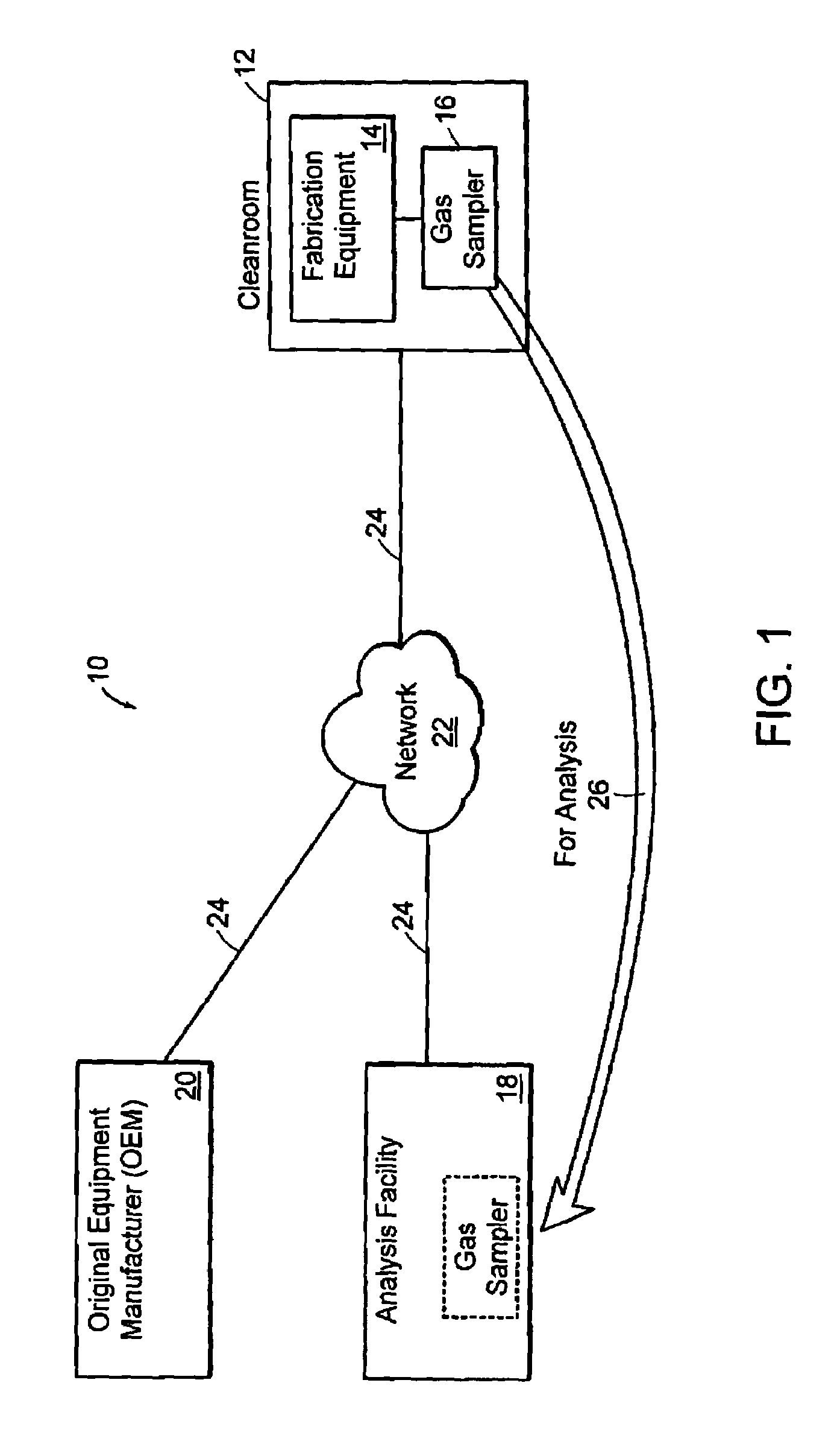
[0044]FIG. 1 contains a schematic representation of a system for measuring and analyzing contaminants using a preferred embodiment of the invention, system 10 includes a cleanroom 12 having semiconductor fabrication equipment 14 operating therein, a gas sampling unit 16, a gas sampler analysis facility 18, an original equipment manufacturer (OEM) 20, a communications network 22, and communications links 24. Cleanroom 12 is used in the manufacture of semiconductor devices, such as silicon wafers. Within cleanroom 12, one or more pieces of fabrication equipment 14 are operating. Examples of fabrication equipment 14 are, but are not limited to, photolithography machines and chemical vapor deposition systems. Gas sampling unit 16 is placed in cleanroom 12 to sample contaminants present therein. Gas sampling unit 16 may be coupled to one or more pieces of fabrication equipment 14 using, for example, Teflon tubing, or gas sampling unit 16 may be located such that it draws ambient cleanroo...


PUM

PropertyMeasurementUnit
volumeaaaaaaaaaa
diameteraaaaaaaaaa
heightaaaaaaaaaa

Abstract

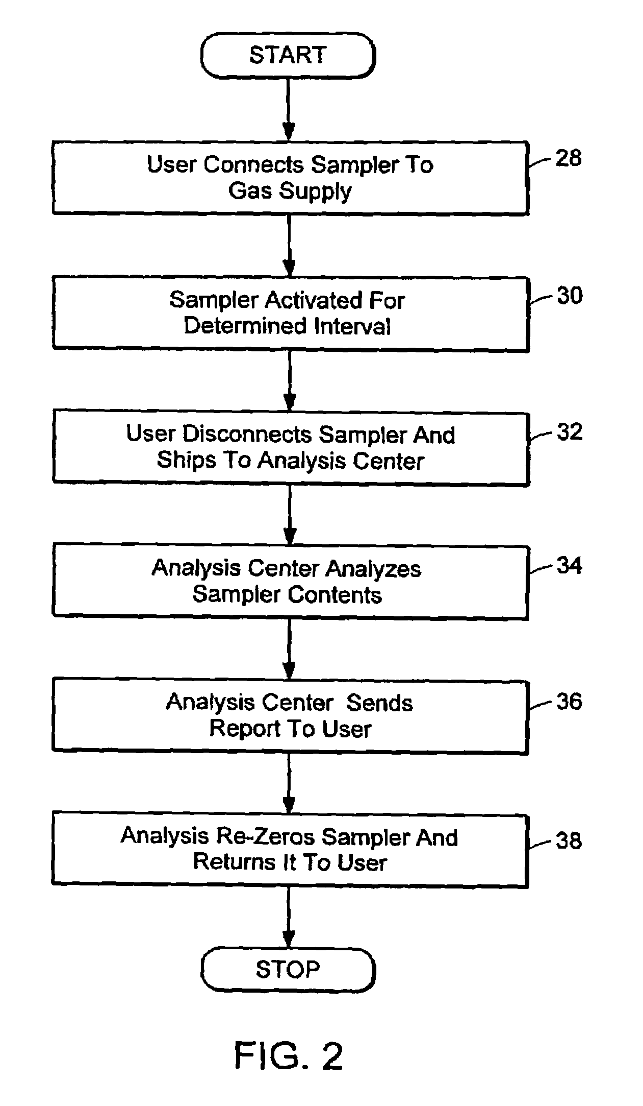
The present invention relates to a system and method for sampling a gas flow to measure one or more contaminants within a semiconductor processing tool. The system includes a portable unit containing one or more dry traps, Tenax traps and, if desired, wet impingers. The unit is coupled to a gas flow in a clean room and the dry traps. Tenax traps and wet impingers measure contaminants contained in the gas supply for a determined sampling interval. When the sampling interval is done, the unit is sent to an analysis facility for processing.

Description

CROSS REFERENCES TO RELATED APPLICATIONS[0001]This patent application claims the benefit of U.S. provisional patent application 60 / 526,862 filed on Dec. 3, 2003, and is a continuation in-part of U.S. application Ser. No. 10 / 933,692 filed Sep. 2, 2004, the entire contents of these applications being incorporated herein by reference.BACKGROUND OF THE INVENTION[0002]Semiconductor manufacturers continue to measure and control the level of contamination in the processing environment, especially during the critical steps of the photolithography processes. The typical means of determining the quality and quantity of contamination in gas samples in cleanroom manufacturing environments involves sampling air and purge gases, such as, for example, filtered and unfiltered air, clean dry air, and nitrogen. One of the most common base contaminants in the air worldwide is ammonia. Within a semiconductor fabrication facility ammonia commonly arises from wet benches, chemical vapor deposition (CVD),...

Claims


Application Information

Patent Timeline
Patent Type & Authority Patents(United States)
IPC IPC(8): G01N1/22B01D53/22G01N1/10G01N1/24G01N33/00H01L21/00
CPCB01D53/22B01D63/00G01N1/2214H01L21/67253B01D2313/18G01N1/2205G01N1/2273G01N1/24G01N2001/1093
Inventor GRAYFER, ANATOLYLOBERT, JURGEN MICHAELGOODWIN, WILLIAMBELANGER, FRANK VINCENTSERGI, JOHN E.PHELPS, MARK C.
Owner ENTEGRIS INC
Learn More