Plotting board with magnetic pivot

a technology of pivoting and plotting boards, applied in the field of plotting boards, can solve the problems of often fractured disks and obstacles to effective use of rulers, and achieve the effect of minimizing plotting errors and easy removal and reattaching

Inactive Publication Date: 2008-09-30
UNITED STATES OF AMERICA THE AS REPRESENTED BY THE SEC OF THE ARMY
View PDF13 Cites 2 Cited by
  • Summary
  • Abstract
  • Description
  • Claims
  • Application Information

AI Technical Summary

Benefits of technology

[0006]It is another object of the invention to provide a plotting board having a top that is easily removed and reattached.
[0007]It is a further object of the invention to provide a plotting board wherein the top is held tightly to the bottom to minimize plotting error.

Problems solved by technology

When the disk is removed from the base, the disk often fractures.
Furthermore, because a soldier may slide a ruler across the base when plotting a fire mission, the presence of the vertical pin is an obstacle to effective use of the ruler.

Method used


Image

  • Plotting board with magnetic pivot
  • Plotting board with magnetic pivot

Examples


Embodiment Construction

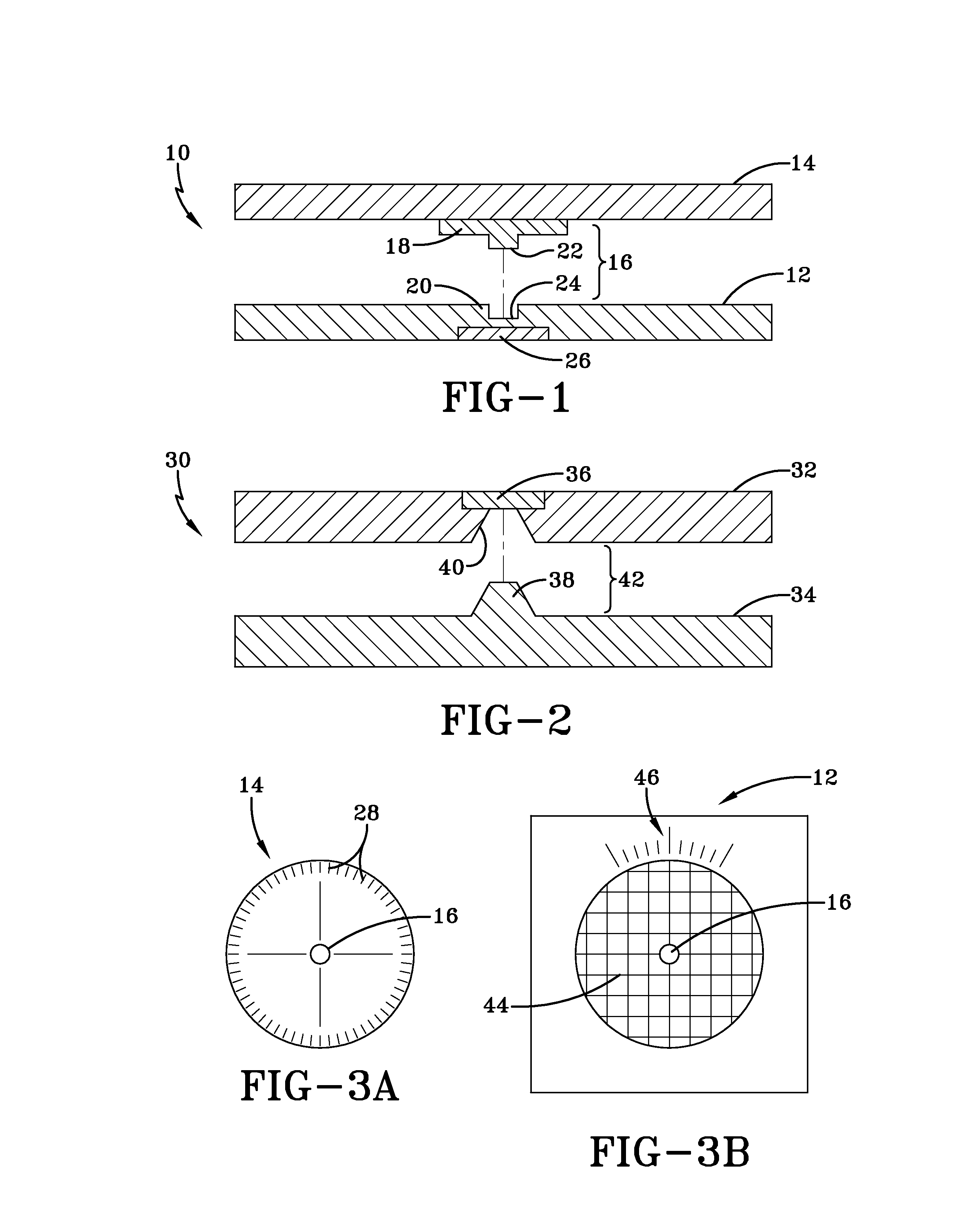
[0016]In one embodiment, the apparatus of the invention is a plotting board for use in calculating and plotting fire missions. However, the apparatus may be used in other applications as well.

[0017]FIG. 1 is a schematic side view of one embodiment of a plotting board 10 in accordance with the invention. Board 10 includes a base 12, a top 14 and a pivot 16 that connects the top 14 and the base 12. Base 12 and top 14 are preferably plate-like members. In FIG. 1, the pivot 16 comprises male and female mating portions 18, 20. The male portion 18 is shown on the top 14 and the female portion 20 is shown on the base 12. However, the positions of the male and female portions may be reversed. The male portion 18 of the pivot 16 is disposed substantially at the center of the top 14. The male portion 18 comprises a cylinder 22 and the female portion 20 comprises a cylindrical opening 24 for receiving the cylinder 22. The top 14 is rotatable and detachable with respect to the base 12.

[0018]The...


PUM


Abstract

A plotting board includes a base; a top; a pivot that connects the top and the base, the top and the base being rotatable and detachable with respect to each other, the pivot including a magnet wherein at least a portion of the pivot is disposed at a substantially central point on the top.

Description

CROSS-REFERENCE TO RELATED APPLICATIONS[0001]This application claims the benefit under 35 USC 119(e) of U.S. provisional patent application 60 / 595,569 filed on Jul. 15, 2005, which is hereby incorporated by reference.STATEMENT OF GOVERNMENT INTEREST[0002]The inventions described herein may be manufactured, used and licensed by or for the U.S. Government for U.S. Government purposes.BACKGROUND OF THE INVENTION[0003]The invention relates in general to munitions and in particular to plotting boards used to plot firing missions for a munition.[0004]Soldiers may use a plotting board to calculate and plot firing missions for, for example, a mortar weapon system. The method of using the plotting board is known. A known plotting board comprises a base with a vertical pin or axle in its center. A top disk has a central hole and fits over the vertical pin in the base. The top disk also has a retaining clip to keep the disk in place. When the disk is removed from the base, the disk often fract...

Claims


Application Information

Patent Timeline
IPC IPC(8): B43L9/16G01C21/22
CPCG01C21/22Y10S33/01
Inventor BECK, JR., ROBERT F.MAKHIJANI, AMIT J.MONICO, JASON P.TILLINGHAST, RALPH C.
Owner UNITED STATES OF AMERICA THE AS REPRESENTED BY THE SEC OF THE ARMY
Why Eureka
Try Eureka