Device for gripping and displacing material, such as roughage

a technology for displacing and grabbing materials, applied in the direction of animal feeding devices, load-engaging elements, conveyor parts, etc., can solve the problems of material parts falling unintentionally from the gripping device during transport or during lifting of the gripper, material falling over or into the machinery may also form a hazard for the continued operation of the machinery, and the risk of unintentional spillage from the gripping device is always presen

Inactive Publication Date: 2008-09-09
LELY ENTERPRISES
View PDF23 Cites 4 Cited by
  • Summary
  • Abstract
  • Description
  • Claims
  • Application Information

AI Technical Summary

Benefits of technology

[0007]The present invention addresses these problems by providing a device for gripping and displacing material comprising: a gripper for gripping and subsequently displacing the material; a collecting device comprising a collecting element for collecting material falling unintentionally from the gripper; an actuator for actuating the gripper from an open position to a gripping position; and an operating element for independently moving the collecting element between an inactive position in which the gripper may be actuated to grip material and an active position in which the collecting element is able to collect material that is lost unintentionally by the gripper. In this context, independent movement of the collecting element is understood to encompass all movement thereof that is not concurrent with movement of the gripper between open and gripping positions. Thus, the movement of the collecting element may take place as a consequence of e.g. the completion of movement of the gripper. Similarly, interlocks may be provided to prevent movement of the collecting element unless the gripper is in a particular position.
[0014]According to a yet further inventive feature, operation may take place using e.g. the signal from the level sensor in such a way that, if the material to be gripped is located at different levels, the material located at the highest or almost the highest level will always be the first to be gripped. Additionally or alternatively, the material may be dropped at that place where the level of the material dropped is the lowest or almost the lowest. In this way a sensible distribution of material is maintained.
[0015]According to again another inventive feature, the gripper may be connected to a suspension device. The suspension device is preferably displaceable e.g. along a rail or by mounting thereof on an autonomous vehicle. The latter embodiment has the advantage that the material can be displaced via a freely determinable route.
[0019]The device may form part of a feeding installation comprising a feeding column provided with one or more feed troughs and with a chute hopper for dropping the material gripped by the gripper. The feeding column may be provided with a metering mechanism for metering, from the chute hopper, the material to be supplied to the feed trough(s). The installation may further be provided with a content-determining device for determining the weight and / or the volume of the material present in the feeding column. It is further advantageous if the installation comprises an alarm device and / or a make-and-break device that emits a signal if there is little or no material left to be gripped by the gripper. In this manner it is possible that the device is put out of operation temporarily and / or that the attention of an operator is drawn to the fact that there is no material left to be picked up by the device. There may also be provided weighing means with the aid of which the amount of material gripped and / or dropped is determined.

Problems solved by technology

However, if the bucket-gripper is not completely closed, for example owing to material parts being clamped between the two bucket halves, the risk of material parts falling unintentionally from the gripping device during transport or during lifting of the gripper always remains.
Unintentional spillage from a grab is particularly inconvenient where the grab must pass over areas where it is not desired that material should fall.
This is particularly the case in automated environments where operators may not be available to tidy up.
Material falling over or into machinery may also form a hazard for continued operation of the machinery.

Method used


Image

  • Device for gripping and displacing material, such as roughage
  • Device for gripping and displacing material, such as roughage
  • Device for gripping and displacing material, such as roughage

Examples


Embodiment Construction

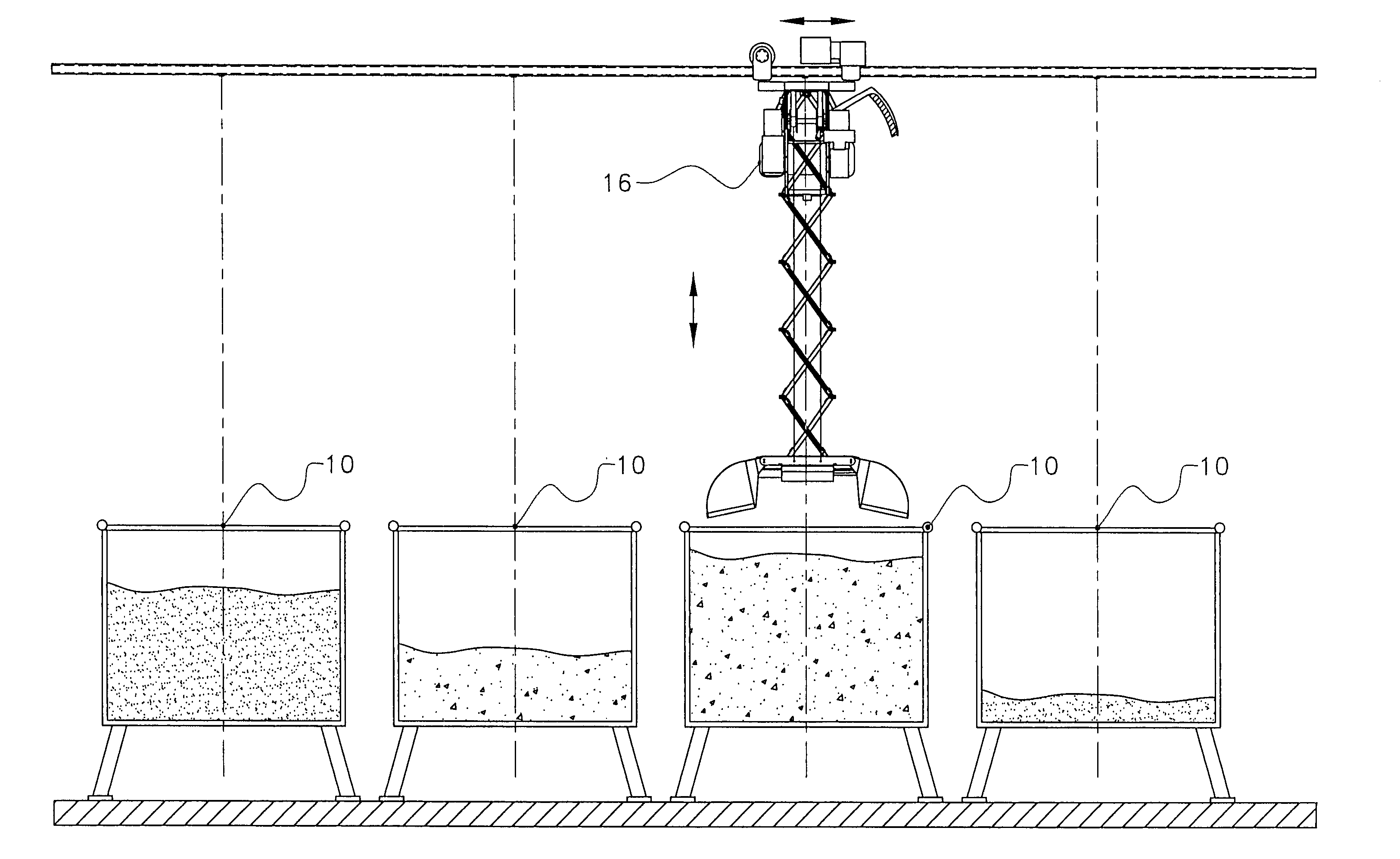
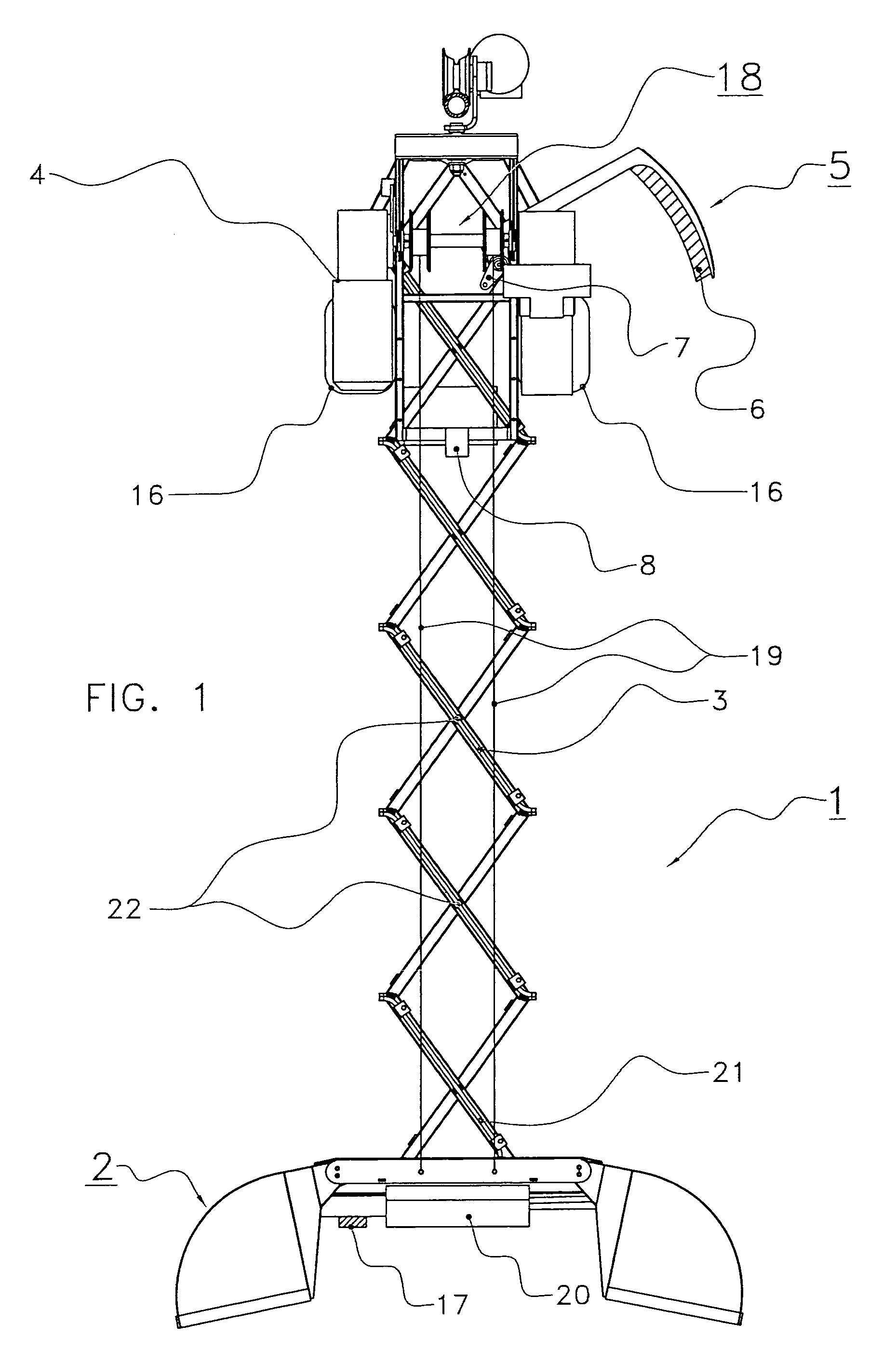
[0027]FIG. 1 is a side view of a gripping device 1 for gripping and displacing material, such as roughage for animals for example, which device is provided with a gripper 2 designed in the present embodiment as a bucket-gripper. However, it will be obvious that, instead of a bucket-gripper, it will also be possible to apply other suitable gripping elements, such as a fork-gripper for example; the choice of the gripping elements largely depends on the material to be gripped. The gripper 2 is connected to a displaceable suspension device 4 by means of an accordion-like hingeable arm construction 3.

[0028]The accordion-like hingeable arm construction 3 serves to stabilise the gripper 2 in its extended position. Sideward movements of the gripper 2 are limited by means of such a construction. For this purpose, the separate hingeable arms are connected in their middle, in a way in which they are rotatable relative to one another, about pivot axes 22.

[0029]The gripping device 1 is further p...


PUM


Abstract

A device for gripping and displacing material, such as roughage for animals, which device is provided with a gripper (2) for gripping and subsequently displacing the material, and with a collecting device (5) comprising a collecting element (6) for collecting material falling unintentionally from the gripper (2). The device is further provided with an operating element (7) such that, after the material has been gripped by the gripper (2), the collecting element (6) is capable of being brought from an inactive position into a further position in which the collecting element (6) is able to collect material that is lost unintentionally by the gripper (2).

Description

CROSS REFERENCE TO RELATED APPLICATIONS[0001]This application claims priority from Netherlands application number 1024326 filed on 19 Sep. 2004, the contents of which are hereby incorporated by reference in their entirety.BACKGROUND OF THE INVENTION[0002]1. Field of the Invention[0003]The invention relates generally to a device for gripping and displacing material, such as roughage for animals, in particular to such a device provided with a gripper for use in combination with a feeding column for distributing feed to a number of animals.[0004]2. Description of the Related Art[0005]Devices are known for gripping and displacing material. Such devices may comprise a pair of articulated grabs suspended from a gantry or the like. Different forms of grab e.g. buckets, forks, clamps etc may be used according to the type of material to be displaced. Gripping devices are also known in which a first fork-gripper is surrounded by a double bucket-gripper. By means of the fork-gripper large piec...

Claims


Application Information

Patent Timeline
Patent Type & Authority Patents(United States)
IPC IPC(8): B66C3/02A01K5/02
CPCB66C3/02A01K5/02
Inventor BOS, GREORGIUS RUDOLPHIUS
Owner LELY ENTERPRISES
Why Eureka
Try Eureka