Pivotal bar-lock with encased cylinder lock

a bar-lock and cylinder lock technology, applied in the field of bar-locks, can solve the problems of inconvenient use, misplaced, and difficult to find protected hasp locks,

Inactive Publication Date: 2008-08-19
DOLEV MOSHE
View PDF18 Cites 7 Cited by
  • Summary
  • Abstract
  • Description
  • Claims
  • Application Information

AI Technical Summary

Benefits of technology

[0019]An advantage of the present invention is that the entire locking bar serves as a locking bolt.
[0020]In one embodiment of the present invention, the locking means is a channel having formed therein a first locking bay defined as a closed position locking bay, and a second locking bay defined as an open position locking bay, the first and second locking bays being disposed at opposing ends of the channel.
[0021]When the locking bar is pivoted to engage the mating element of the locking hasp, the channel engages a locking cam in the closed position locking bay, locking the pivotal bar-lock.
[0022]When the locking bar is pivoted to disengage from the mating element and the locking hasp, the channel engages the locking cam in the open position locking bay, thus securing the locking bar in the open position.
[0023]A feature of the invention is the design of the locking cam, which is formed with a partial circumferential collar, with the collar being supported on the cylinder lock, thereby eliminating forced-opening pressure acting on an internal mechanism associated with the cylinder lock.
[0024]An additional feature of the invention is that the collar is formed with at least one notch which engages a spring-loaded plunger, to define at least one of the open, in-transit and closed positions.

Problems solved by technology

With advances in technological developments, the locking function of the bar-lock was limited to locking stables, barns, sheds, and the like, where the brace locks the doors from the outside and prevents the exit of livestock from secure areas.
Protected hasp locks, such as that described, are inconvenient to use.
This is because once the padlock is opened, the padlock body and shackle must be stored until the lock is re-closed, and they may be misplaced and difficult to find.
In addition, it is inconvenient and sometimes difficult for a user to operate the prior art padlock with only one hand free, since it needs both hands in order hold the lock body at the same time as using a key.

Method used


Image

  • Pivotal bar-lock with encased cylinder lock
  • Pivotal bar-lock with encased cylinder lock
  • Pivotal bar-lock with encased cylinder lock

Examples


Embodiment Construction

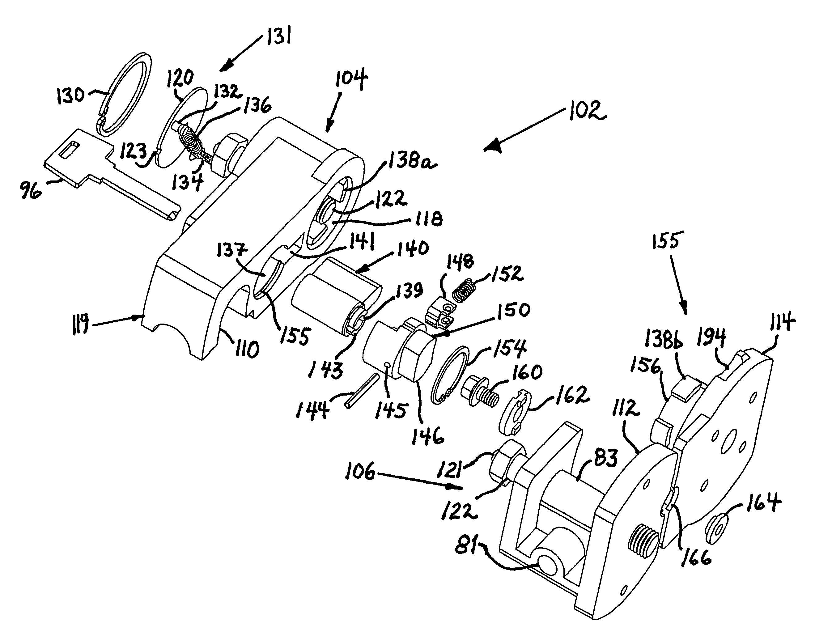
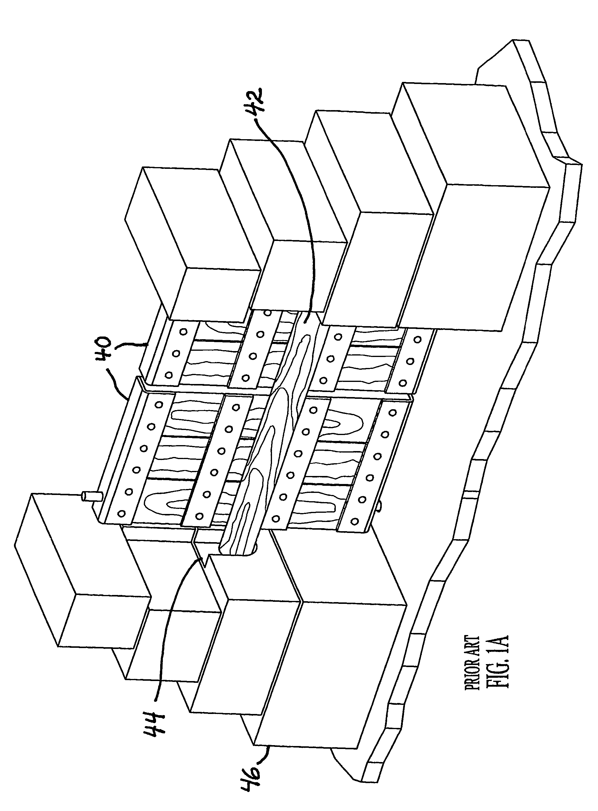
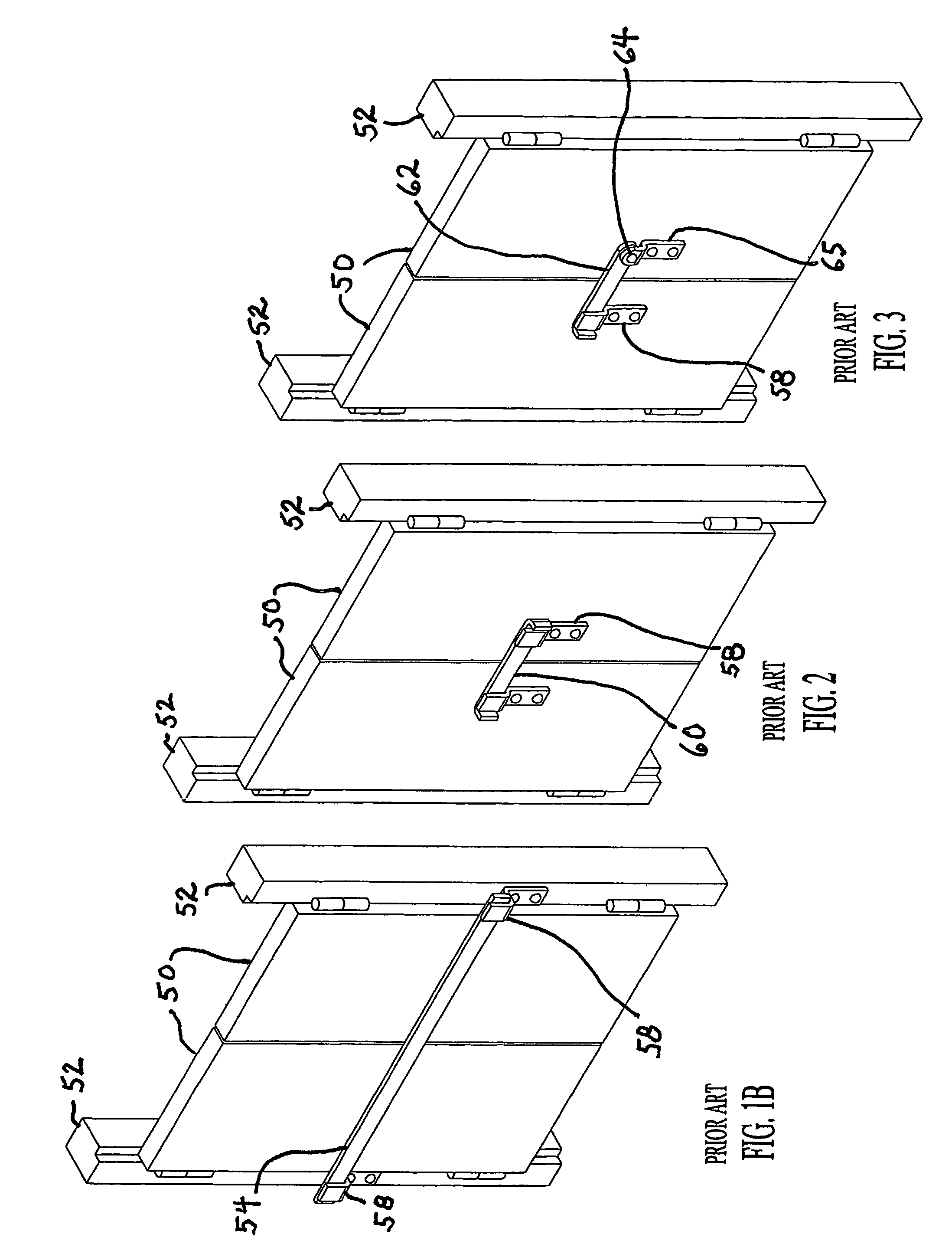
[0084]Referring now to FIG. 1A there is shown an example of an ancient prior art configuration of fortified, double doors 40 barred with a timber member 42 which is secured within keepers 44 formed in the stone walls 46. In FIGS. 1B and 2-4, there are shown alternative prior art configurations of double doors 50 with supporting door posts 52 adapted to use simple bars 54, 60, 62, 66, and 67, respectively, for securing the doors in a closed, barred condition. In FIG. 1B, the bar 54 is mounted between the doorposts 52 using bar keepers 58 to hold bar 54 securely in place. In FIG. 2, a short bar 60 is mounted across the doors 54 and secured in place using bar keepers 58 attached directly to double doors 50. In FIG. 3, bar 62 is pivotal about an axis 64 of a bar anchor 65 and secured in bar keeper 58, both bar keeper 58 and bar anchor 65 being mounted on double doors 50. In FIG. 4, double doors 50 are barred with a pivotal bar 66 rotatable at axis 64 of bar anchor 65 which is mounted to...


PUM


Abstract

A pivotal bar-lock comprising an anchor hasp having a locking hub and a first locking element integrally formed with a first mounting plate; a locking hasp integrally formed with a second mounting plate and having a mating element and a second locking element formed therein; and a locking bar rotatably mounted on the anchor hasp, the locking bar having a cylinder lock encased therein and an engagement element formed therewith, the cylinder lock being operable such that when rotated into an unlocked mode, the locking bar is pivotally enabled to assume one of open, in-transit, and closed positions in interaction with the first and second locking elements, and when the cylinder lock is rotated into a locked mode, the engagement element of the locking bar engages the mating element of the locking hasp.

Description

FIELD OF THE INVENTION[0001]The present invention relates generally to bar-locks, and more particularly to an encased bar-lock provided with a cylinder lock mounted on a pivotal bar, enabling barring and locking functions with a high degree of security against tampering and breakage.BACKGROUND OF THE INVENTION[0002]The bar-lock is a type of lock known for thousands of years. This type of lock was in use in ancient walled cities, in which a large brace, typically a piece of timber wood, or an entire tree trunk, was placed against the width of a gate from the inside, the gate normally opening inward as shown in prior art FIG. 1A. In later prior art, a metal bar was placed in U-shaped or L-shaped anchor braces fastened to each side of the gate posts to hold the bar firmly against the gate, thus preventing the gate from opening, as shown in prior art FIG. 1B. With advances in technological developments, the locking function of the bar-lock was limited to locking stables, barns, sheds, a...

Claims


Application Information

Patent Timeline
Patent Type & Authority Patents(United States)
IPC IPC(8): E05B67/38E05B9/08E05B13/10E05B17/20E05B63/12E05B65/16E05C3/04E05C7/00E06B
CPCE05B9/08E05B13/10E05B17/2034E05B17/2049E05B17/2053E05B63/127E05C3/04E05C3/044E05B63/12E05B17/2084E05C7/04E05B83/10E05C3/041E05C7/00Y10T70/358Y10T70/498Y10T70/30Y10T70/375
Inventor DOLEV, MOSHE
Owner DOLEV MOSHE
Why Eureka
Try Eureka