
Temperature-measuring device with function indicator

a technology of temperature measurement and function indicator, which is applied in the direction of instruments, heat measurement, diagnostic recording/measuring, etc., can solve the problems of dual temperature sensor separation from the skin surface and interruption of temperature measuremen

Active Publication Date: 2008-08-12
DRAGERWERK AG
View PDF27 Cites 27 Cited by
  • Summary
  • Abstract
  • Description
  • Claims
  • Application Information

AI Technical Summary

Benefits of technology

The present invention provides a temperature-measuring device with a dual temperature sensor that can detect changes in temperature on the skin surface and the environment. The device includes an evaluating means that compares the measured temperature values from the two sensors to determine the body core temperature and the contact of the dual temperature sensor with the skin surface. The evaluating means can also determine the similarity of the signals from the two sensors to indicate the contact. The device can be used to monitor the body temperature of patients with a simple and cost-effective design.

Problems solved by technology

If the dual temperature sensor is not arranged properly or if there is increased physical activity, it may happen that the dual temperature sensor separates from the skin surface and the temperature measurement is interrupted.

Method used


Image

  • Temperature-measuring device with function indicator
  • Temperature-measuring device with function indicator
  • Temperature-measuring device with function indicator

Examples


Embodiment Construction

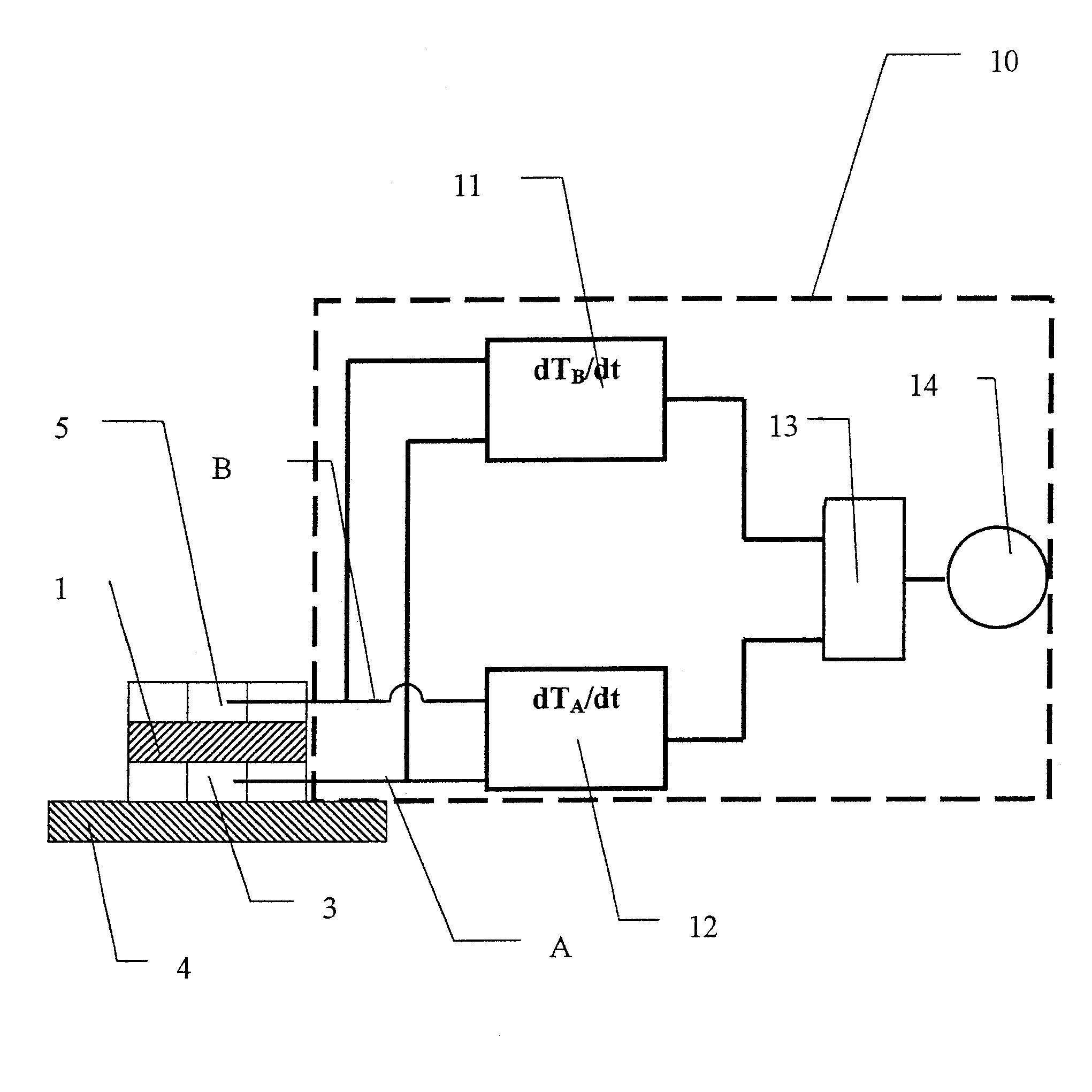
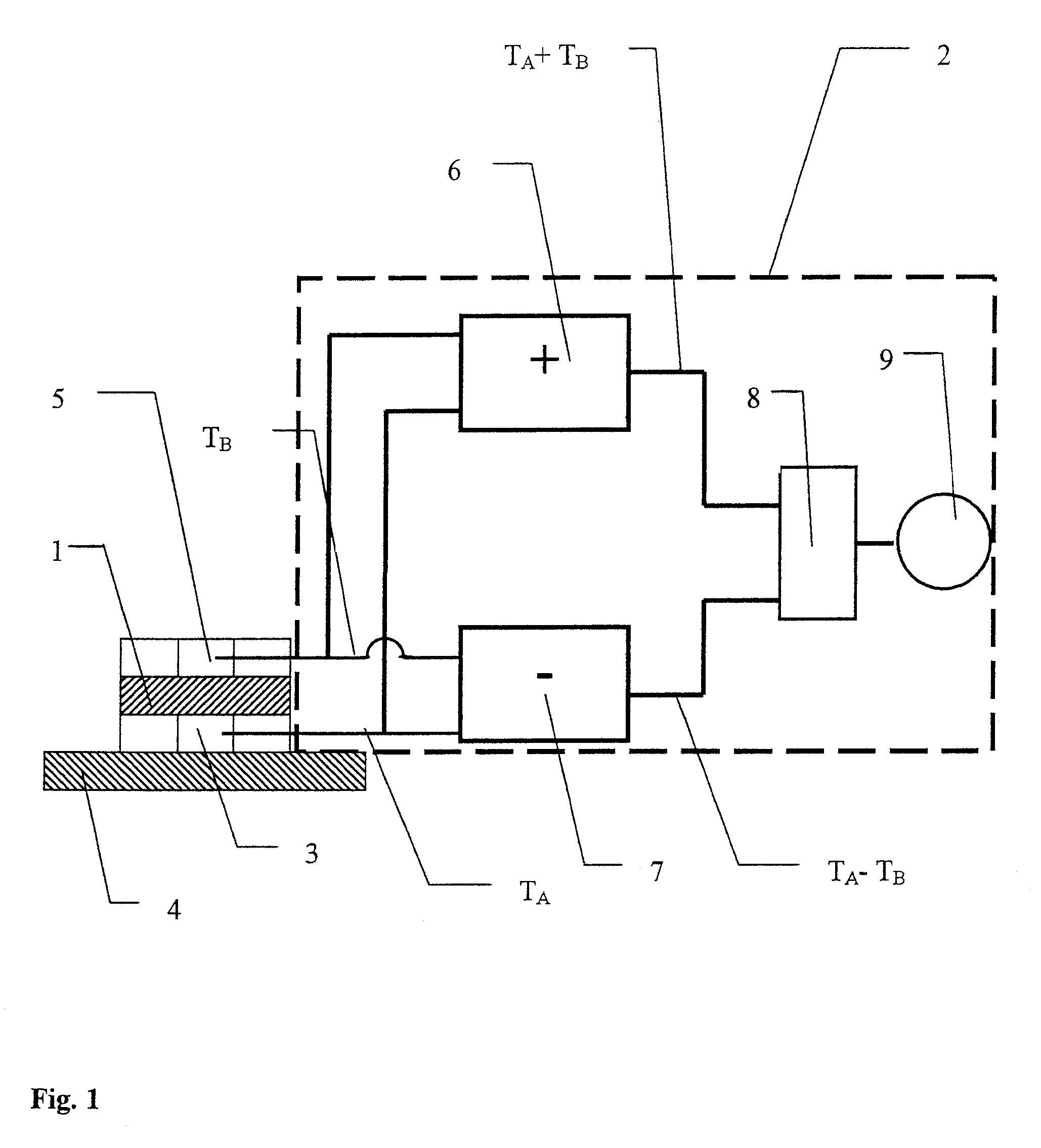
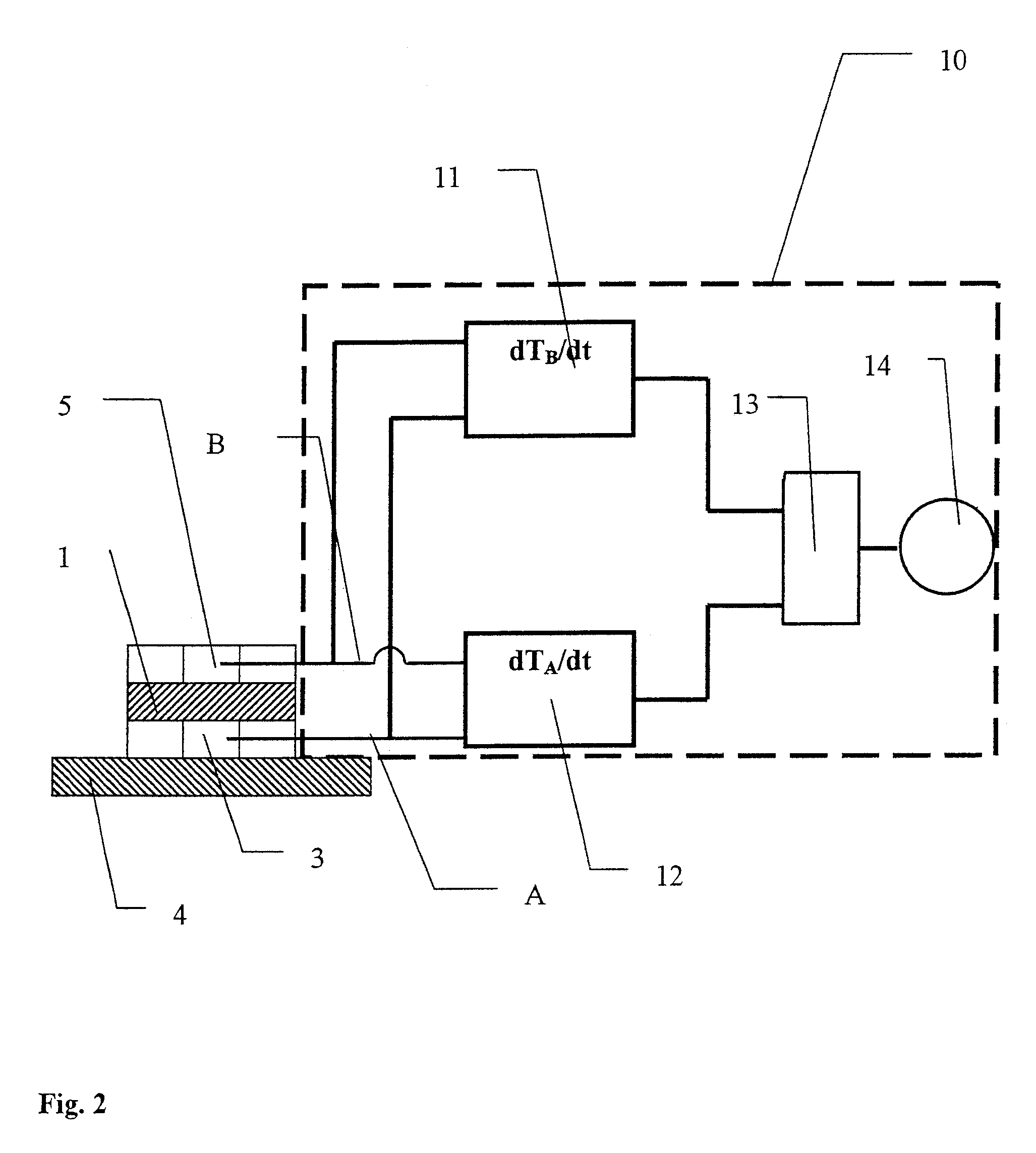
[0023]Referring to the drawings in particular, FIG. 1 schematically illustrates the design of a dual temperature sensor 1 and of an evaluating circuit 2, which is connected to the dual temperature sensor 1. The dual temperature sensor 1 contains a first temperature sensor 3, which is in contact with the skin surface 4 of a patient, not shown in greater detail, and a second temperature sensor 5, which is arranged in such a way that it is thermally insulated against the first temperature sensor 3. The first temperature sensor 3 detects the temperature of the skin surface 4 in channel A as a first measured temperature value TA, while the second temperature sensor 5 in channel B with the second measured temperature value TB is thermally coupled with the temperature in the environment of the measuring point. The evaluating circuit 2 contains a summation element 6 for forming a sum, TA plus TB, from the measured temperature values TA and TB, and a subtraction element 7 for determining a d...


PUM

PropertyMeasurementUnit
temperatureaaaaaaaaaa
thermal conductivityaaaaaaaaaa
physical activityaaaaaaaaaa

Abstract

A function indicator for a dual temperature sensor, which indicates the falling off of the sensor from the skin surface (4) of a patient. An evaluating device (2) determines the body temperature from a first measured temperature value (TA) and determines the contact of the dual temperature sensor (1) with the skin surface (4) by comparison of the measured temperature values TA and TB.

Description

CROSS REFERENCE TO RELATED APPLICATIONS[0001]This application claims the benefit of priority under 35 U.S.C. § 119 of German Patent Application DE 10 2005 037 921.4 filed Aug. 11, 2005, the entire contents of which are incorporated herein by reference.FIELD OF THE INVENTION[0002]The present invention pertains to a temperature-measuring device with a first temperature sensor and with a second temperature sensor, which are arranged in the form of a dual temperature sensor opposite each other, wherein either the first temperature sensor or the second temperature sensor is in contact with the skin surface of a patient for detecting a first measured temperature value, while the temperature sensor arranged opposite with the second measured temperature value is thermally coupled with the temperature in the environment of the measuring point.BACKGROUND OF THE INVENTION[0003]A temperature-measuring device with a dual temperature sensor is known from DE 101 39 705 A1. In the prior-art dual te...

Claims


Application Information

Patent Timeline
Patent Type & Authority Patents(United States)
IPC IPC(8): G01K1/20A61B5/01A61B5/276
CPCG01K1/20G01K13/002G01K7/42G01K13/20G01K7/427A61B5/276
Inventor KOCH, JOCHIM
Owner DRAGERWERK AG
Learn More