
Method of steering aircraft by moving the stagnation point and aircraft using the method

a technology of aircraft and stagnation point, which is applied in the direction of rigid airships, aircraft navigation control, air-cushion, etc., can solve the problems of difficult and expensive implementation, complex aircraft, and difficult and complicated steering of aircraft at different operational stages, and achieve the difficulty of making such an aircraft operate reliably enough

Inactive Publication Date: 2008-08-05
LIGHTWAY
View PDF20 Cites 18 Cited by
  • Summary
  • Abstract
  • Description
  • Claims
  • Application Information

AI Technical Summary

Benefits of technology

"The present invention provides a new method and aircraft for steering and controlling the movement of an aircraft. The method involves using a fan means to create a circulation of air that is directed along the housing of the aircraft. The fan means can adjust the blow direction and force to achieve the desired circulation. The aircraft can also have a stagnation point associated with the circulation to further control its movement. The invention allows for versatile and efficient operation of the aircraft with a simple structure. The technical effects of the invention include improved steering and control of the aircraft, as well as increased efficiency and space utilization."

Problems solved by technology

Consequently the aircraft becomes complex and therefore difficult and expensive to implement.
Furthermore, the steering of the aircraft at different operational stages becomes extremely complicated and difficult.
It is extremely difficult to make such an aircraft operate reliably enough and so that it provides adequate lift.
In addition, steering such an aircraft is very complicated and difficult.
The structure of such an aircraft is very complex and difficult to implement and also difficult to steer.
The structure of this aircraft is also very complex and the steering thereof is complicated and difficult.

Method used


Image

  • Method of steering aircraft by moving the stagnation point and aircraft using the method
  • Method of steering aircraft by moving the stagnation point and aircraft using the method
  • Method of steering aircraft by moving the stagnation point and aircraft using the method

Examples


Embodiment Construction

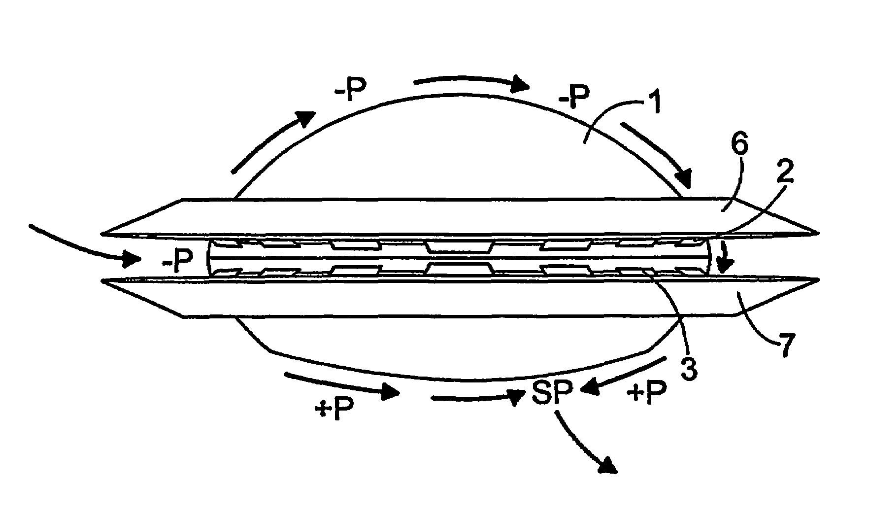
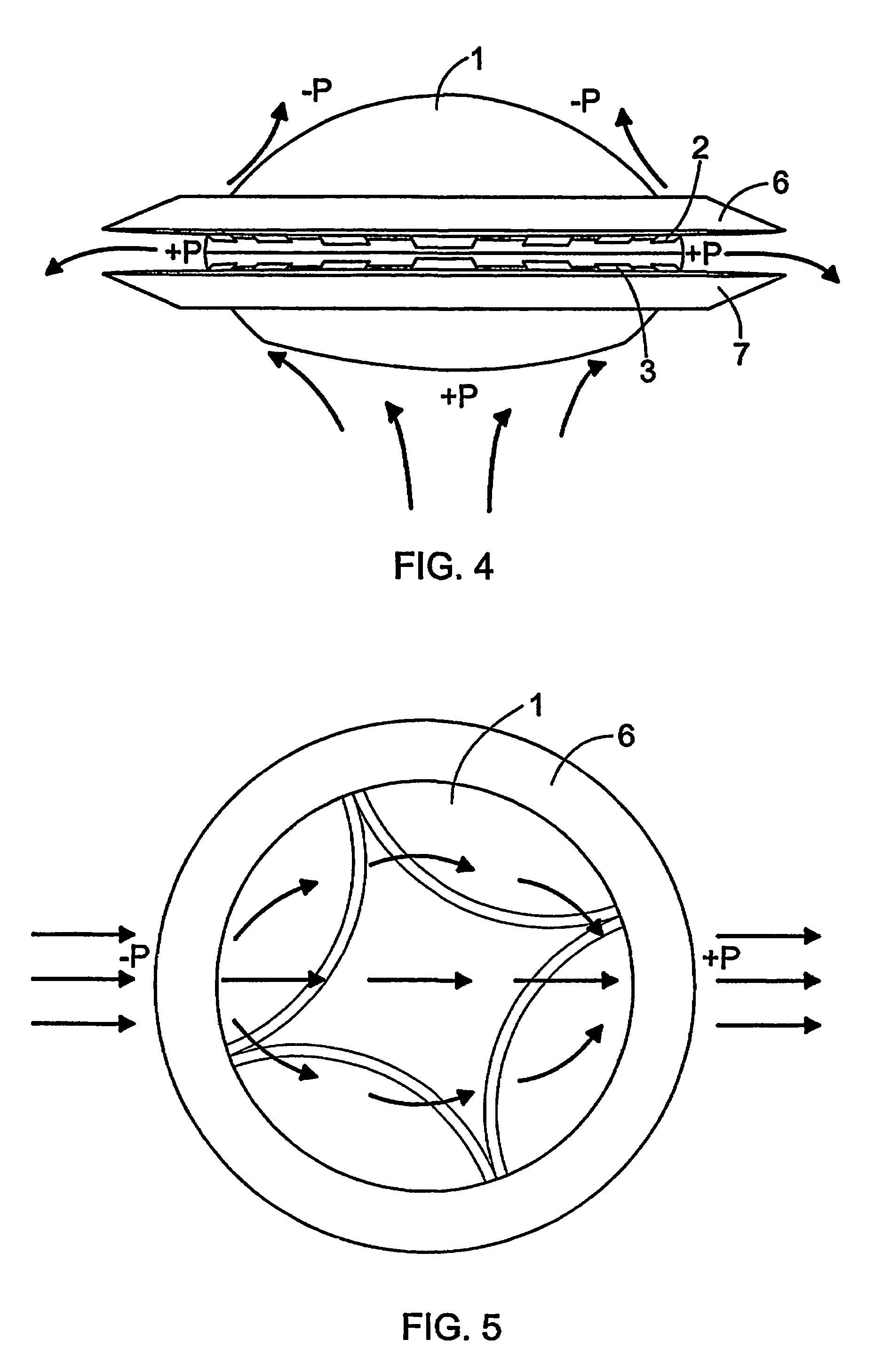
[0037]FIG. 1 shows an aircraft comprising a housing 1 that is more convex on the upper surface thereof than on the lower surface thereof. Upper fan blades 2 and lower fan blades 3 are arranged about the housing 1. The upper fan blades 2 are fastened to an upper rotating ring 4 and the lower fan blades 3 are fastened to a lower rotating ring 5. The rotating rings 4 and 5 enable to rotate the fan blades 2 and 3 about the housing 1. Preferably the fan blades 2 and 3 are rotated in opposite directions, whereby the operation of the aircraft becomes stable.

[0038]The aircraft also comprises an upper air spoiler 6 and a lower air spoiler 7. Rotating the fan blades 2 and 3 and adjusting the blade angles thereof enable the fan blades 2 and 3 to direct air between the housing 1 and the air spoilers 6 and 7. The air spoilers 6 and 7 are immovably fastened in relation to the housing 1.

[0039]When taking off with the aircraft, the blade angles of the fan blades 2 and 3 are arranged to be positive,...


PUM


Abstract

An aircraft which includes elements providing air circulation and directing the circulation along a housing. Different operational stages of the aircraft such as take off and level flight are achieved by using the same functionally inter-connected elements. The circulation is achieved by fan elements that allow adjusting the blow direction and the blowing force of the flow. A stagnation point (SP) associated with the circulation is also formed if necessary below the housing and the aircraft can be steered by controlling the circulation and the position of the stagnation point (SP).

Description

BACKGROUND OF THE INVENTION[0001]The invention relates to a method of steering an aircraft comprising a housing and fan means.[0002]The invention also relates to an aircraft comprising a housing and fan means.BRIEF DESCRIPTION OF THE INVENTION[0003]Publication WO 01 / 94 199 discloses an aircraft provided with a housing that is circular in shape as viewed from above. Rotatable rings comprising vanes provided with adjustable blade angles are arranged about the housing. Rotating the rings and adjusting the blade angles appropriately allow the aircraft to lift in the vertical direction. After take-off during level flight the vanes in the rings are turned in the horizontal direction and the jet engines at the sides of the housing generate forward thrust during level flight. Separate means are therefore used during take-off and level flight, whereby the aircraft has to employ various mechanisms. Consequently the aircraft becomes complex and therefore difficult and expensive to implement. F...

Claims


Application Information

Patent Timeline
Patent Type & Authority Patents(United States)
IPC IPC(8): B64C29/00B64C39/00
CPCB64C39/001
Inventor KIRJAVAINEN, KARI
Owner LIGHTWAY
Learn More