
Floodlight featuring dual bracket with integral strap tensioning and wire splicing

a technology of wire splicing and brackets, which is applied in the direction of contact members penetrating/cutting insulation/cable strands, coupling device connections, lighting support devices, etc., to achieve the effect of eliminating the need for wire connectors and labor

Inactive Publication Date: 2008-07-22
XYLEM IP HLDG
View PDF11 Cites 31 Cited by
  • Summary
  • Abstract
  • Description
  • Claims
  • Application Information

AI Technical Summary

Benefits of technology

[0013]Another advantage of the present invention is that the tab welding operation in the prior art is hence eliminated.
[0014]The new and unique floodlight also provides for a significant reduction in the labor time associated with the installation of the bracket mounted floodlight on marine vessel and non-marine vessel installations, where a bracket is mounted to round, elliptical or other shaped solid bars or tubing of various diameters and cross-sectional shapes and dimensions. This design eliminates the need to weld a mounting tab to the tubing to which the bolted brackets are currently mounted. The design also eliminates the need for wire connectors and the labor associated with wire stripping, connector crimping and / or soldering when making electrical connections to the bracket mounted products.

Problems solved by technology

The known bracket mounted products or floodlights suffer from the need to weld a mounting tab to the tubing to which bolted brackets are currently mounted, as well as the need for wire connectors and the labor associated with wire stripping, connector crimping and / or soldering when making electrical connections to the bracket mounted products.

Method used


Image

  • Floodlight featuring dual bracket with integral strap tensioning and wire splicing
  • Floodlight featuring dual bracket with integral strap tensioning and wire splicing
  • Floodlight featuring dual bracket with integral strap tensioning and wire splicing

Examples


Embodiment Construction

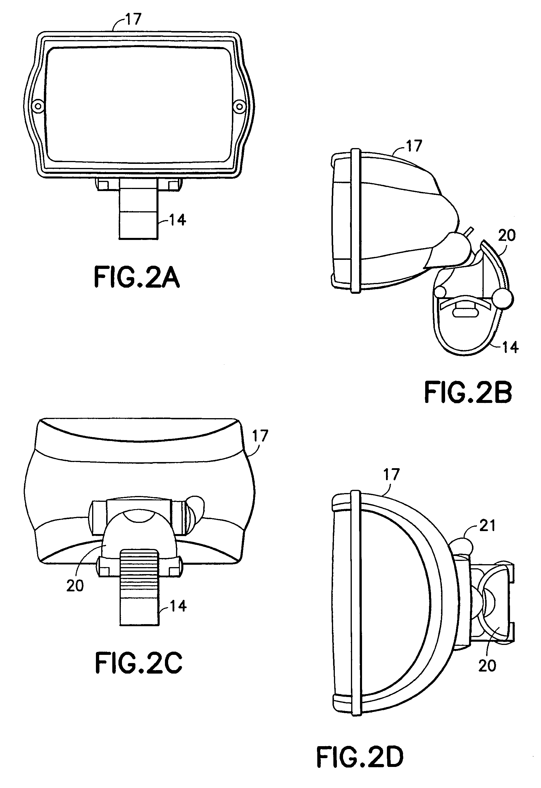
[0023]FIGS. 1-6 show a new and unique floodlight generally indicated as 10 for mounting to a tubing 44 (see FIGS. 3-5). The floodlight 10 features a dual latch bracket generally indicated as 12 having an integral strap tensioning and wire splicing technique according to the present invention, for mounting a bulb enclosure assembly 17 of the floodlight 10 to a variety of different tubing shapes and sizes. It is important to note that, although the invention is described in relation to a floodlight having such a dual latch bracket for mounting the same, the scope of the invention is intended to include or other suitable bracket mounted products or devices.

[0024]The floodlight 10 includes a dual latch bracket having various parts and elements generally indicated as 12 and a corresponding mounting arrangement having various parts or elements generally indicated as 15.

[0025]For example, the mounting arrangement 15 includes a mounting base 16 adapted for supporting the bulb enclosure asse...


PUM


Abstract

A bracket mounted product, such as a floodlight, is provided having a dual latch bracket with integral strap tensioning and wire splicing for mounting on tubing or another suitable mounting structure, featuring a mounting arrangement and a splicing latch arrangement. The mounting arrangement has a mounting base for supporting the light or other suitable product or device on the tubing or another suitable mounting structure, and has a mounting strap for wrapping around the tubing or other suitable mounting structure. The splicing latch arrangement has a swing arm or splicer pivotally arranged on the mounting base for receiving the one or more wires when in an open latch position and for splicing the one or more wires to the internal leads in the mounting base when pivotally rotated to a closed latch position, and also has a mounting lock lever pivotally arranged on the mounting base for receiving the mounting strap when in an open lever position and for frictionally engaging and holding the same when pivotally rotated into a closed latch position for coupling the light to the tubing or another suitable mounting structure.

Description

CROSS-REFERENCE TO RELATED APPLICATION[0001]This application is related to and claims benefit to provisional application Ser. No. 60 / 621,138, filed Oct. 22, 2004, which is hereby incorporated by reference in its entirety.BACKGROUND OF THE INVENTION[0002]1. Technical Field[0003]The present invention relates to a bracket mounted product, including a floodlight; and more particularly, to a bracket mounted product, including a searchlight for a marine vessel or other suitable non-marine vessel.[0004]2. Description of Related Art[0005]Many different bracket mounted products, including floodlights, are known in the art for marine and non-marine vessels; however, no bracket mounted product or floodlight is known having one or more of the unique features shown and described herein. The known bracket mounted products or floodlights suffer from the need to weld a mounting tab to the tubing to which bolted brackets are currently mounted, as well as the need for wire connectors and the labor as...

Claims


Application Information

Patent Timeline
Patent Type & Authority Patents(United States)
IPC IPC(8): H01R4/24F21W107/20
CPCB60Q1/0483B60Q1/24B63B17/00F21V27/00F21V21/116B63B45/02F21V21/30B60Q1/245
Inventor LEBLANC, KENNETH J.COOK, GREGORY S.FROST, OLIVER C.
Owner XYLEM IP HLDG
Learn More