Protective shield assembly for space optics and associated methods

a shield and optics technology, applied in the direction of cosmonautic thermal protection, transportation and packaging, cosmonautic vehicles, etc., can solve the problems of increasing the temperature that re-radiates to the optical surface and electronic assemblies, unable to provide heat protection, and freeing particulate contamination from the interior of the interceptor

Inactive Publication Date: 2008-07-22
THE BOEING CO
View PDF12 Cites 9 Cited by
  • Summary
  • Abstract
  • Description
  • Claims
  • Application Information

AI Technical Summary

Benefits of technology

[0009]The invention addresses the above needs and achieves other advantages by providing a protective shield assembly that is capable of protecting launch vehicle components, such as an optical system, and thereafter further capable of being deployed and, therefore, removed from a launch vehicle, such as a missile. The protective shield assembly includes a shroud and a flexible sheet of material within the shroud that is capable of conforming to the contour of a portion of the launch vehicle that may be susceptible to heat and contaminants. Thus, while the shroud protects the launch vehicle components from external contaminants, the flexible sheet of material protects the launch vehicle components from contaminants originating within the shroud and launch vehicle, as well as heat. When the shroud is deployed, the flexible sheet of material is also advantageously pulled away from the launch vehicle to expose a portion of the launch vehicle, which is typically an optical system, thereby exposing the optical system for operation.
[0015]The present invention therefore provides many advantages. The flexible sheet of material provides a protective layer that may conform about an optical system disposed within a launch vehicle, such as a missile. Providing a flexible sheet of material enables the material to be configured about a variety of launch vehicle components to provide a barrier against heat and contaminants that may otherwise sacrifice the accuracy of the components, such as an optical system. Thus, the incidence of a lower signal-to-noise ratio and blurring due to warped optics may be significantly reduced.
[0016]Furthermore, the flexible sheet of material may be an inexpensive material, such as a polyester film, and may be readily attached to the interior surface of the shroud. Upon deployment of the shroud, the flexible sheet of material is also removed from the launch vehicle, which provides additional protection for the launch vehicle components without affecting the ability of shroud to be deployed from the launch vehicle. Finally, because the flexible sheet of material has a broad area of attachment substantially about the circumference of the shroud, the risk of failure during deployment is greatly reduced when compared with mechanical devices having a single or very few areas of attachment and / or including techniques that have a higher risk of failure during deployment of the shroud.

Problems solved by technology

In particular, during launch and at high speeds, the interceptor is subjected to frictional heating from air passing at high speeds over the interceptor causing increased temperatures that re-radiate to the optical surfaces and electronic assemblies.
In addition, vibration caused during launch and flight frees particulate contamination from the interior of the interceptor that may re-deposit on the optical surfaces.
However, this system cannot provide protection from heat and contamination proximate to the cover itself and its deployment.
However, there is no protective shield between the shroud and the optical window such that the optical window is still susceptible to heat radiation and contamination traveling from the interior of the shroud and through the nose cavity, which increases the probability for blurring of the optical system.
In other words, while the shroud protects the optical window and the optical system that communicates through the optical window from external communication, the optical window is not protected from contamination originating from the shroud itself.

Method used


Image

  • Protective shield assembly for space optics and associated methods
  • Protective shield assembly for space optics and associated methods
  • Protective shield assembly for space optics and associated methods

Examples


Embodiment Construction

[0027]The present invention now will be described more fully hereinafter with reference to the accompanying drawings, in which some, but not all embodiments of the invention are shown. Indeed, this invention may be embodied in many different forms and should not be construed as limited to the embodiments set forth herein; rather, these embodiments are provided so that this disclosure will satisfy applicable legal requirements. Like numbers refer to like elements throughout.

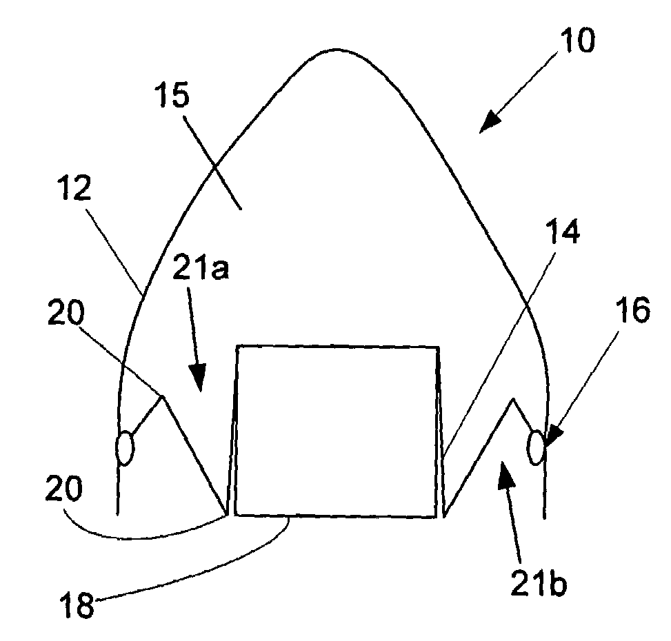
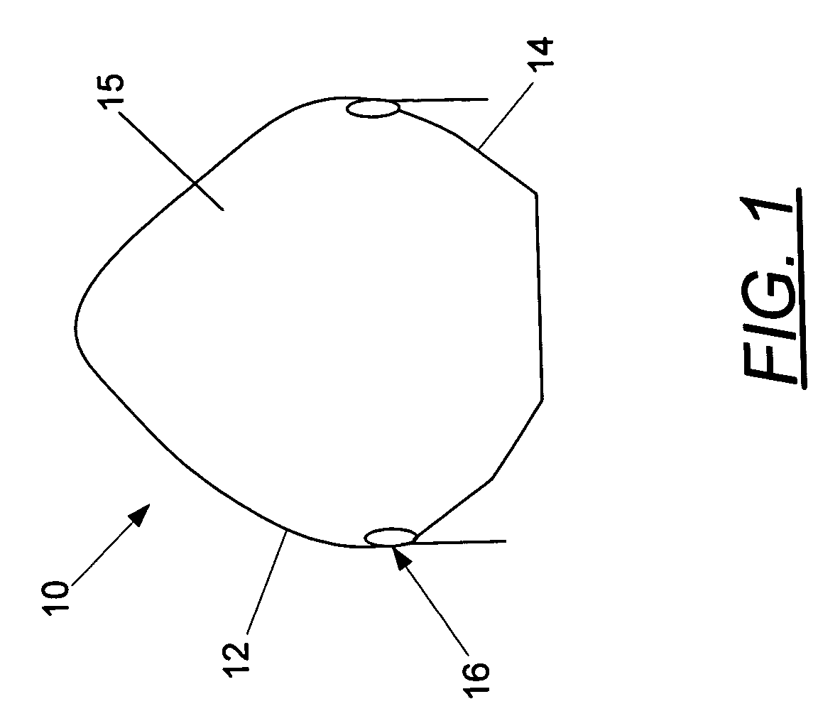
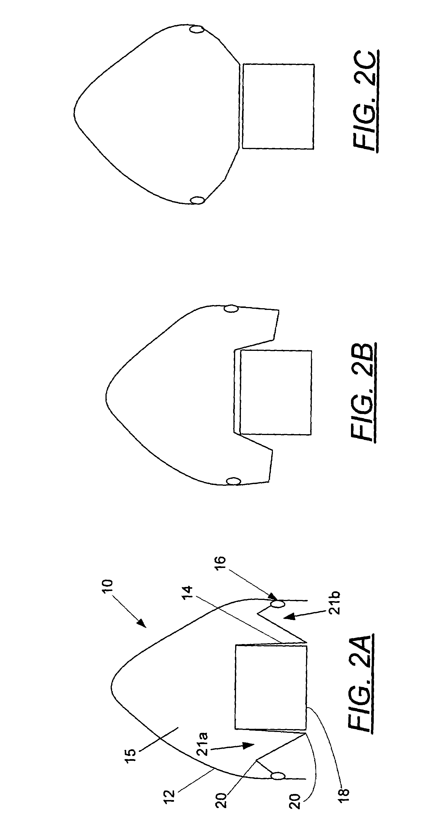
[0028]Referring now to the drawings and, in particular to FIG. 1 there is shown a protective shield assembly 10. The protective shield assembly 10 generally includes a shroud 12 and a flexible sheet of material 14 attached to an interior surface of the shroud. In general, the protective shield assembly 10 is employed to protect launch vehicle components, such as an optical system, that are disposed within the launch vehicle but later exposed when the assembly is deployed and removed from the launch vehicle. Howeve...


PUM

PropertyMeasurementUnit
thicknessesaaaaaaaaaa
flexibleaaaaaaaaaa
lengthaaaaaaaaaa

Abstract

A protective shield assembly capable of being deployed from a launch vehicle is provided, and methods for assembling and deploying the protective shield assembly are also provided. The protective shield assembly includes a shroud, and a flexible sheet of material within the shroud. The flexible sheet of material is capable of substantially conforming to a contour of at least a portion of the launch vehicle to provide a protective barrier.

Description

BACKGROUND OF THE INVENTION[0001]1) Field of the Invention[0002]The present invention relates to a shield for space optics and, more particularly, to a shield for protecting space optics from heat and contamination.[0003]2) Description of Related Art[0004]Interceptors, such as missiles or rockets for air defense, use various techniques for in-flight guidance in order to identify and / or engage airborne objects. If the interceptor is searching for a ballistic missile, the interceptor must not only be capable of tracking the missile but also distinguishing between the missile and any decoys. Examples of in-flight guidance techniques include devices, technologies, and media using infrared or visible cameras or detectors, LADAR, transducers, or other sensors, including sensitive components such as lenses, mirrors, lasers, or fiber optics, to transmit or detect light, other electromagnetic energy such as millimeter waves, or other forms of energy, such as sound waves.[0005]Interceptors th...

Claims


Application Information

Patent Timeline
Patent Type & Authority Patents(United States)
IPC IPC(8): B64G1/52
CPCB64G1/52B64G1/58F42B15/34Y10T29/49622Y10T29/49826
Inventor LUNDGREN, MARK ANDREWSHU, HENRY K.DADSON, CARL FREDERICK
Owner THE BOEING CO
Why Eureka
Try Eureka