Method for the control of a gearbox arrangement

a gearbox and gear arrangement technology, applied in the direction of gearing control, gearing elements, belts/chains/gearrings, etc., can solve the problems of reducing driving comfort, requiring and expensive calibration of the control process to bring the drive clutch into the slip region, and reducing the duration of the entire shift process. , to avoid oscillations or individual torque variation peaks, the effect of reducing the duration of the entire shift process

Active Publication Date: 2008-07-15
DEERE & CO
View PDF16 Cites 0 Cited by
  • Summary
  • Abstract
  • Description
  • Claims
  • Application Information

AI Technical Summary

Benefits of technology

[0009]The torque transmitted by a clutch depends on the engagement pressure with which the clutch is loaded. This is the case particularly with an electromagnetic, hydraulically actuated clutch. The shift bump caused by the shift process of the power shift gearbox is largely compensated for by a brief period of slip of the drive clutch so that the jerking during shifting almost never occurs and the driving comfort is improved. In particular, there is no need to modify the control arrangement of the engine so that problems associated with this are circumvented. The power shift gearbox can also be shifted under load through all gear ratios without completely interrupting the transmission of torque from the engine to the drive axle. By automatically initiating the disengagement process of the drive clutch, an operating error of the gearbox arrangement is largely avoided. By providing a control of the value of the slip of the drive clutch, an individual calibration of the entire gearbox arrangement during the production of the vehicle can be omitted, since during each power shift process an individual control of the value of the slip of the drive clutch is performed. During this control process, actual values are constantly compared to target values provided as an input by the control algorithm. The value of the slip of the drive clutch that can be adjusted individually or controlled correspondingly.
[0015]In order for a gentle and modulated engaging of the drive clutch to be assured, the value of the slip of the drive clutch could be reduced from the time of the start of the power shift process by a predetermined, preferably linear, course of the function. This could also be attained by limiting the value of the slip of the drive clutch in the downward and / or the upward direction starting with the time of the power shift process according to a predetermined linear function by means of the control algorithm, in order to finally avoid oscillations or individual torque variation peaks.

Problems solved by technology

This leads to torque variations in the drive-line of the vehicle, which are felt by the operator of the vehicle as jerk-like motion, thus resulting in reduced driving comfort.
The calibration of the control process to bring the drive clutch into the slip region is costly.
This may be required and is costly, particularly if various vehicle components have different configurations of a power shift gearboxes and drive clutches.

Method used


Image

  • Method for the control of a gearbox arrangement
  • Method for the control of a gearbox arrangement
  • Method for the control of a gearbox arrangement

Examples


Embodiment Construction

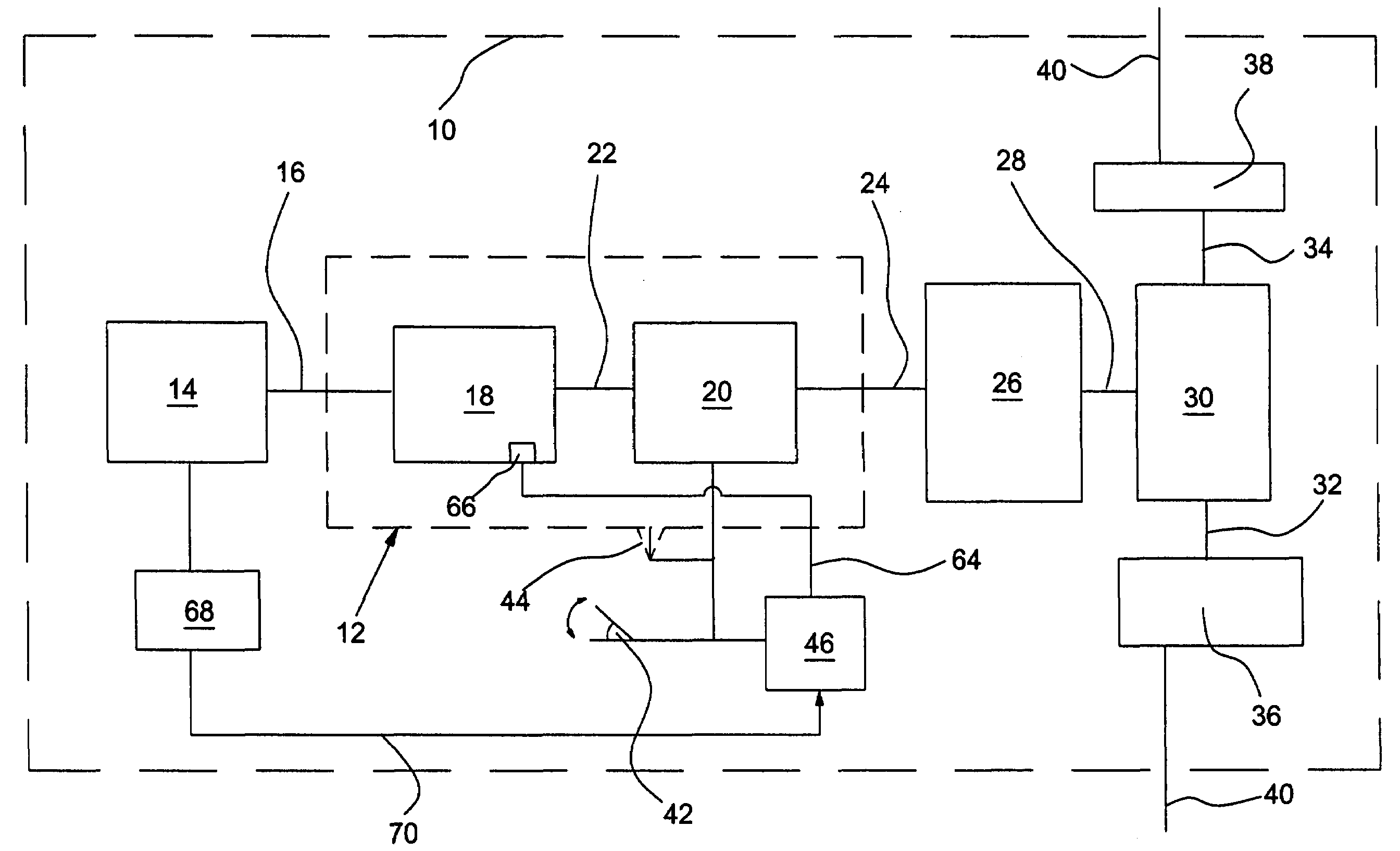
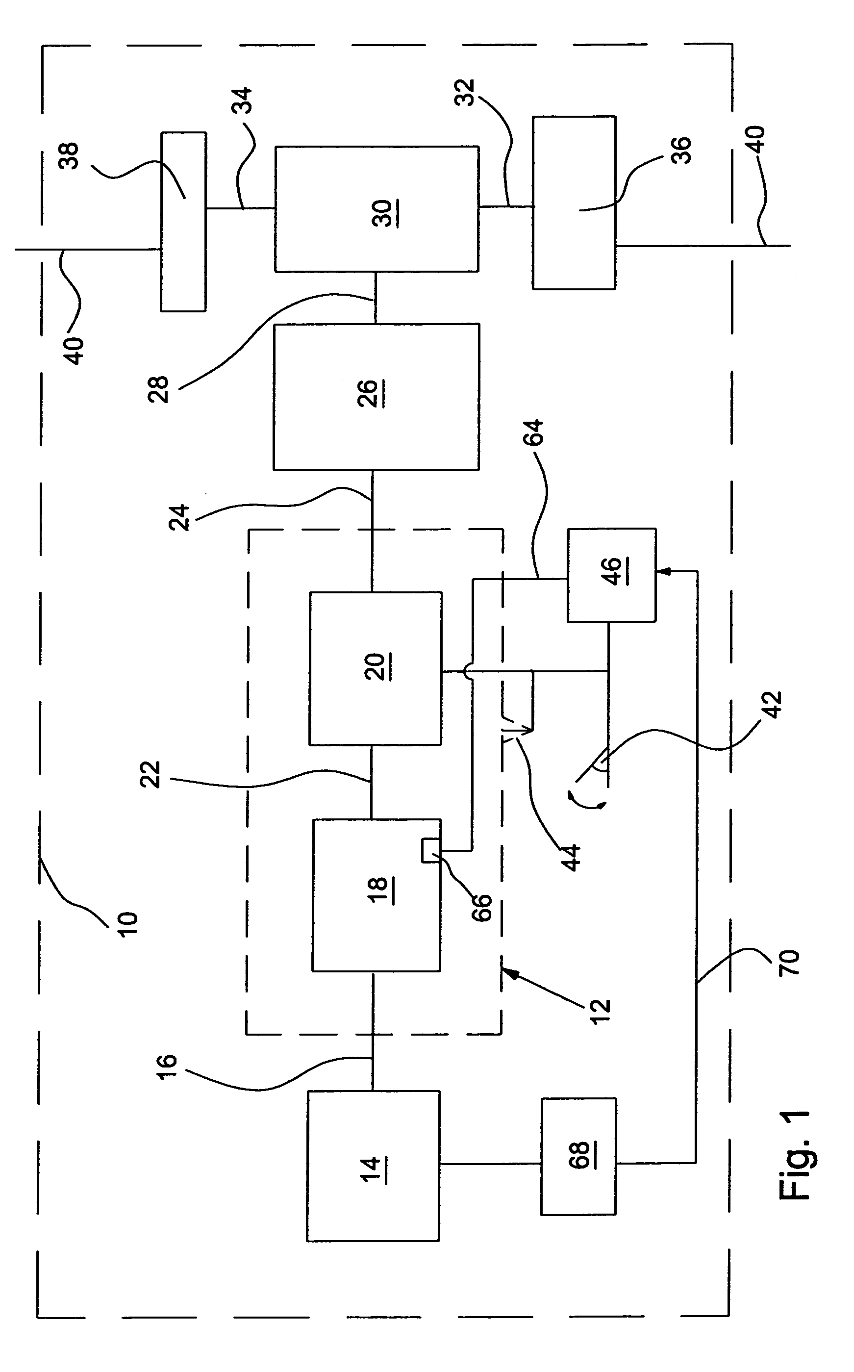
[0026]FIG. 1 shows a vehicle 10 configured in the form of a tractor with a gearbox arrangement 12 according to the invention. The vehicle 10 is driven by a prime mover 14 configured as an internal combustion engine. The torque generated by the engine 14 is initially transmitted to the gearbox arrangement 12 by means of the shaft 16. The gearbox arrangement 12 includes a power shift gearbox 18 and a drive clutch 20 (with a reverse gear ratio) that are connected to each other by means of the shaft 22. The gearbox arrangement 12 is followed by the shaft 24 with a gearbox 26, a so-called group shift gearbox, with which larger speed ranges can be shifted. The shift gearbox 26 is shifted during the actuation of the drive clutch 20, in particular by manual actuation by an operator (not shown in FIG. 1).

[0027]The torque carried by the shift gearbox 26 is transmitted to a differential gearbox 30 by means of a shaft 28. The differential gearbox 30 transmits the torque to a pair of axle gearbo...


PUM


Abstract

The present invention relates to a method for the control of a gearbox arrangement with which a torque generated by an engine is transmitted to a drive axle of a vehicle. The gearbox arrangement includes a power shift gearbox and a drive clutch. During a shift process of the power shift gearbox, the drive clutch is disengaged at least partially so that a remaining torque is transmitted from the engine to the drive axle at an almost unchanged operating condition of the engine.

Description

BACKGROUND[0001]1. Field of the Invention[0002]The present invention relates to methods for the control of a gearbox arrangement by which torque generated by an engine is transmitted to a drive axle of a vehicle which includes a power shift transmission and a reverse module.[0003]2. Description of the Related Art[0004]During the shifting of the power shift gearbox, a jerk during shifting can be felt. This occurs because disk clutches shifting the various gear ratios of the power shift gearbox are engaged and disengaged hydraulically without modulation. This leads to torque variations in the drive-line of the vehicle, which are felt by the operator of the vehicle as jerk-like motion, thus resulting in reduced driving comfort. To avoid the jerking during shifting, U.S. Publication 2004 / 0237682 proposes that the drive clutch be brought purposefully into the slip region in a controlled sequence during the power shift process and subsequently be brought into engagement in a controlled an...

Claims


Application Information

Patent Timeline
Patent Type & Authority Patents(United States)
IPC IPC(8): F16H59/00
CPCF16H61/0437Y10T74/19251F16H2061/0462F16H2061/0425
Inventor REINARDS, MARCO
Owner DEERE & CO
Why Eureka
Try Eureka