Objective lens driving apparatus and optical disc apparatus

a driving apparatus and optical disc technology, applied in the direction of data recording, instruments, disposition/mounting of heads, etc., can solve the problems of increasing the dispersion of the driving force driving the objective lens driving apparatus, the height of the branch yoke is equal or less than one half the height of the cut-up portion, and the distribution of magnetic flux density becomes non-uniform in a height direction, so as to improve the efficiency of the magnetic circuit, improve the symmetry of the magnetic flux density

Inactive Publication Date: 2008-07-08
HITACHI MEDIA ELECTORONICS CO LTD
View PDF6 Cites 2 Cited by
  • Summary
  • Abstract
  • Description
  • Claims
  • Application Information

AI Technical Summary

Benefits of technology

[0007]The present invention is made by taking the problem in the prior art mentioned above into consideration, and an object of the present invention is to make a magnetic flux density distribution of an objective lens driving apparatus close to symmetry, thereby increasing an efficiency of a magnetic circuit. The other object of the present invention is to provide an optical pickup or an optical disc apparatus which can record and reproduce an information at a high speed by using an objective lens driving apparatus having an improved symmetric property of the magnetic flux density and a high efficiency of the magnetic circuit.
[0029]In accordance with the present invention, since a hole portion fitting the second yoke thereto is provided in a bottom portion of the yoke used in the objective lens driving apparatus, and the branch yokes are formed in the second yoke, it is possible to set a thickness and a height of the branch yokes to predetermined values, it is possible to improve a symmetric property of a magnetic flux density distribution, and it is possible to improve an efficiency of a magnetic circuit. Further, since the optical pickup or the optical disc apparatus is provided with the objective lens driving apparatus in which the symmetric property of the magnetic flux density distribution and the efficiency of the magnetic circuit are improved, it is possible to record or reproduce the information at a high speed.

Problems solved by technology

In other words, since the cut-up portion is manufactured in such a manner that the heights of the branch yokes are uniform while taking an uniformity of the magnetic circuit into consideration, it is unavoidable that the height of the branch yoke is equal to or less than one half of the height of the cut-up portion.
However, in accordance with these methods, in the case that the height of the branch yoke is reduced, a distribution of magnetic flux density becomes non-uniform in a height direction, and a dispersion of a driving force driving the objective lens driving apparatus is increased.
Further, if the branch yoke becomes thin, a cross sectional area of a magnetic path becomes small, an efficiency of a magnetic circuit is lowered, and a complex working step is required.
As a result, it is impossible to increase the driving force of the objective lens driving apparatus on the basis of any method.

Method used


Image

  • Objective lens driving apparatus and optical disc apparatus
  • Objective lens driving apparatus and optical disc apparatus
  • Objective lens driving apparatus and optical disc apparatus

Examples


embodiment 1

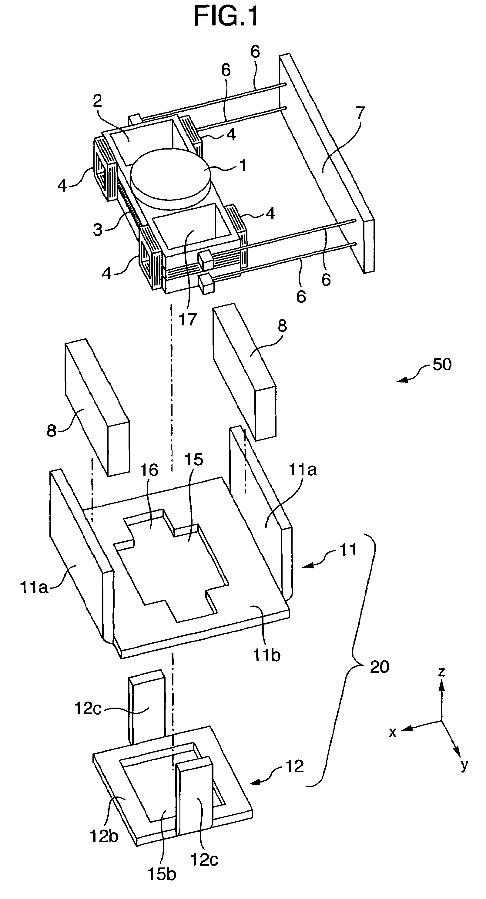
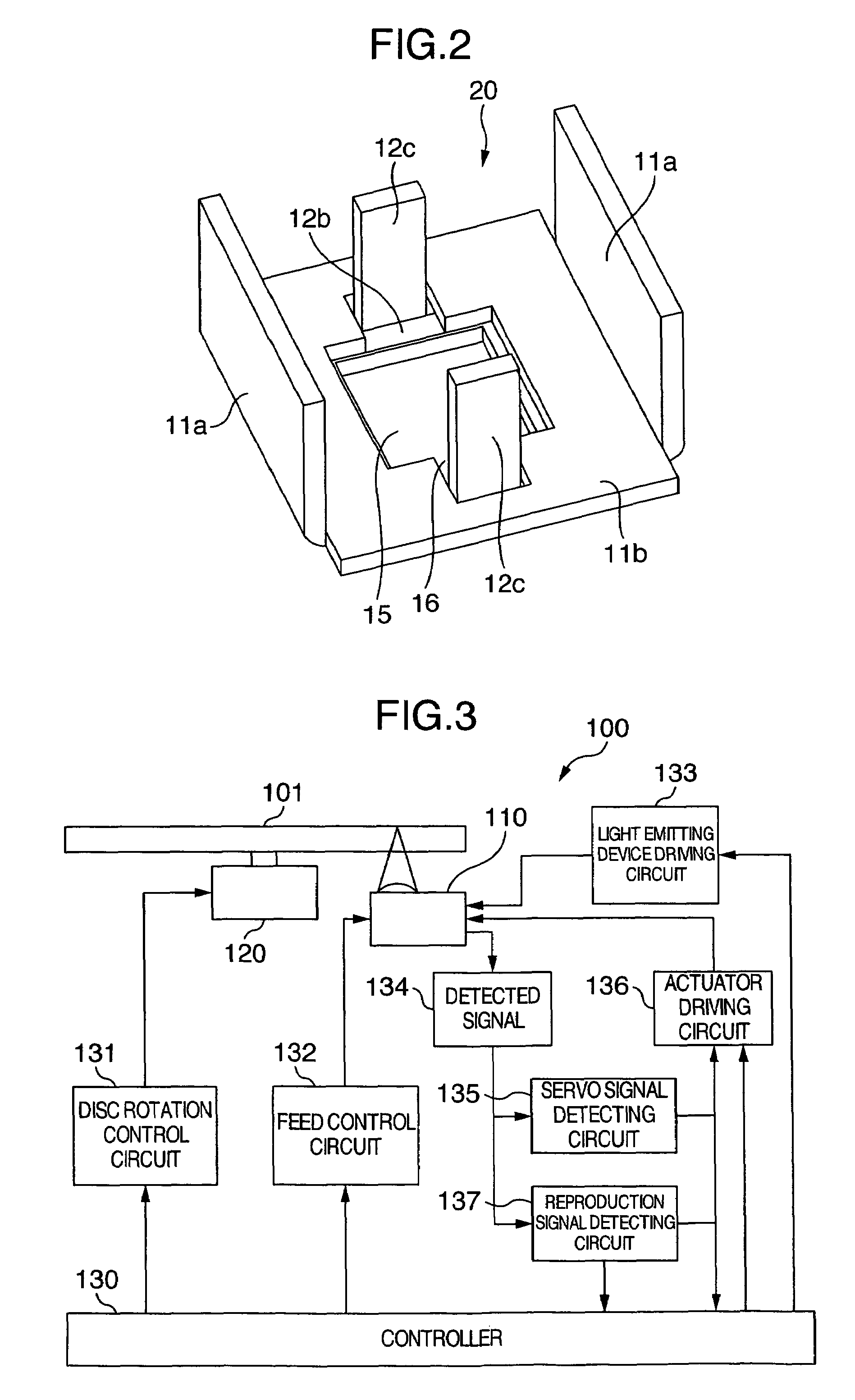
[0040]FIG. 3 shows a block diagram of an optical disc apparatus 100 in accordance with the present invention. The optical disc apparatus 100 is provided with a spindle motor 120 rotating an optical disc 101, and an optical pickup 110 reading an information from the optical disc or writing an information on the optical disc. The optical pickup has an objective lens driving apparatus mentioned in detail later, and an optical part such as a laser light emitting device or the like. The optical pickup 110 and the spindle motor 120 are controlled by a controller 130.

[0041]A disc rotation control circuit 131 is connected to the controller 130. The disc rotation control circuit 131 rotationally drives the spindle motor 120 mounting the optical disc 101 thereon on the basis of a command from the controller 130. A feed control circuit 132 is also connected to the controller 130. The feed control circuit 132 moves the optical pickup 110 in a radial direction of the optical disc 101 on the basi...

embodiment 2

[0057]A description will be given of the other embodiment of a yoke 20 in accordance with the present invention with reference to FIGS. 4 and 5. FIG. 4 is an exploded perspective view of the yoke 20, and FIG. 5 is a perspective view of an assembly thereof. In the present embodiment, as is different from the embodiment shown in FIG. 1, an area of an opening 25 of a first yoke having an outer yoke 21a is made large, and a bottom surface portion 22b of a second yoke 22 is fitted to the opening 25. Further, in order to prevent the second yoke 22 from taking out from the opening 25 of the first yoke 21, a width in an x direction of a notch portion 26 formed in the opening 25 of the first yoke 21 is made narrower than a width in an x direction of an inner yoke 22c.

[0058]In other words, an anglewise protruding portion is formed in a lower portion of the inner yoke 22c, and the heights of the first yoke 21 and the second yoke 22 are positioned by aligning the protruding portion with the bo...

embodiment 3

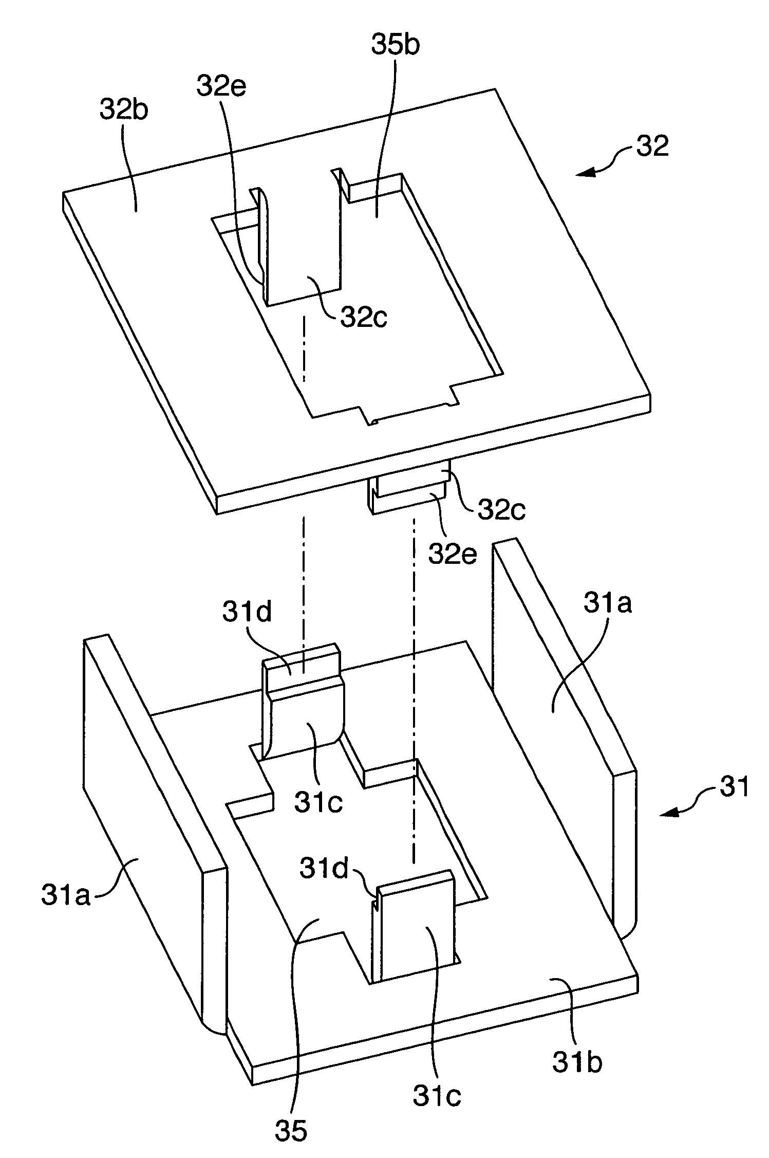
[0060]A description will be given of further the other embodiment of the yoke in accordance with the present invention with reference to FIGS. 6 to 8. FIG. 6 is an exploded perspective view of an objective lens driving apparatus 50, and FIGS. 7 and 8 are exploded perspective views of a yoke. In these drawings, the yoke is constituted by two yoke members in the same manner as the embodiments mentioned above, however, a direction of combining the yokes is different from each of the embodiments.

[0061]The yoke 50 has a lower yoke 31 and an upper yoke 32. The lower yoke 31 is approximately the same as the first yoke 11 described in the embodiment 1, however, a first inner yoke 31c is also formed in this lower yoke 31. The first inner yoke 31c is formed at a time of forming an opening 35 in a bottom plate portion 31b, and is formed by bending a part of the bottom plate portion 31b in the same direction as an outer yoke 31a.

[0062]In the upper yoke 32, a shape of a bottom plate portion 32b...


PUM

PropertyMeasurementUnit
rotating speedaaaaaaaaaa
speedaaaaaaaaaa
driving forceaaaaaaaaaa

Abstract

The invention provides an objective lens driving apparatus in which an efficiency of a magnetic circuit is improved by making a magnetic flux density distribution of the objective lens driving apparatus close to symmetrical. An objective lens driving apparatus has an objective lens, a tracking coil driving the objective lens in a tracking direction, a focusing coil driving the objective lens in a focusing direction, and a yoke arranged so as to oppose to the tracking coil and having a permanent magnet attached thereto. The yoke has a bottom plate portion and an outer yoke bent approximately perpendicularly to the bottom plate portion from an outer edge portion of the bottom plate portion, has a first yoke having an opening formed in a center portion thereof, and a second yoke having a bottom plate portion and an inner yoke bent approximately perpendicularly to the bottom plate portion from an inner edge portion of the bottom plate portion, and having an opening formed in a center portion thereof.

Description

BACKGROUND OF THE INVENTION[0001]The present invention relates to an optical disc apparatus reading an information recorded on a recording surface of an optical disc and recording an information, and an optical pickup and an objective lens driving apparatus used therefore.[0002]In the optical disc apparatus, in order to make recording and reproducing speeds of the information high, there has been known a method of making a rotating speed of the optical disc high. In accordance that the optical disc rotates at a higher speed, it is necessary to increase a driving force generated in a focusing coil and a tracking coil in order to make the objective lens driving apparatus to track the optical disc rotating at a high speed.[0003]Accordingly, in order to increase the driving force of the objective lens driving apparatus, for example, in an optical disc apparatus described in patent document 1 (JP-A-2003-168230 (page 9, FIG. 9)), two branch yokes branched from a magnetic yoke are provided...

Claims


Application Information

Patent Timeline
Patent Type & Authority Patents(United States)
IPC IPC(8): G11B7/00G11B7/09
CPCG11B7/0935G11B7/0933
Inventor KIMURA, KATSUHIKOOGASAWARA, HIROSHISAITO, HIDENAO
Owner HITACHI MEDIA ELECTORONICS CO LTD
Why Eureka
Try Eureka