
Method and a system for monitoring and regulating the power consumed by a transport system

a technology of transport system and monitoring system, which is applied in the direction of transportation and packaging, locomotives, batteries/cells, etc., can solve the problems of high additional costs and unfavorable acquisition of companies operating these transport systems, and achieve the effect of reducing the quality of service rendered and optimizing operating costs

Active Publication Date: 2008-07-08
ALSTOM TRANSPORT TECH SAS
View PDF9 Cites 21 Cited by
  • Summary
  • Abstract
  • Description
  • Claims
  • Application Information

AI Technical Summary

Benefits of technology

[0004]The object of the present invention is therefore to provide a method of monitoring and regulating the power and the energy consumed by a transport system which limits the peak power and energy demands from the electrical power supply network, in order to optimize operating costs, without significantly reducing the quality of service rendered to users. Another object of the invention is to provide a system for implementing the above method.

Problems solved by technology

Transport systems such as underground railway, tram, trolleybus and guided road vehicle systems have high power requirements which are unevenly distributed through the day and essentially consist of the traction power that is dissipated by the vehicles of the system.
It is therefore not advantageous for companies operating these transport systems to acquire their own electrical power stations to supply electrical power, since the power stations would have to be rated to cater for the peak power in the rush hours, and would rarely be operated at their maximum efficiency.
However, most power distribution company price structures take account of a nominal power and energy specified in a contract negotiated with the client, and they bill clients for high additional costs whenever the power or the energy consumed by the client exceeds the nominal power or energy.

Method used


Image

  • Method and a system for monitoring and regulating the power consumed by a transport system
  • Method and a system for monitoring and regulating the power consumed by a transport system
  • Method and a system for monitoring and regulating the power consumed by a transport system

Examples


Embodiment Construction

[0030]To facilitate a reading of the drawings, only the elements necessary to understanding the invention are shown. The same elements are identified by the same reference numbers in all figures in which they appear.

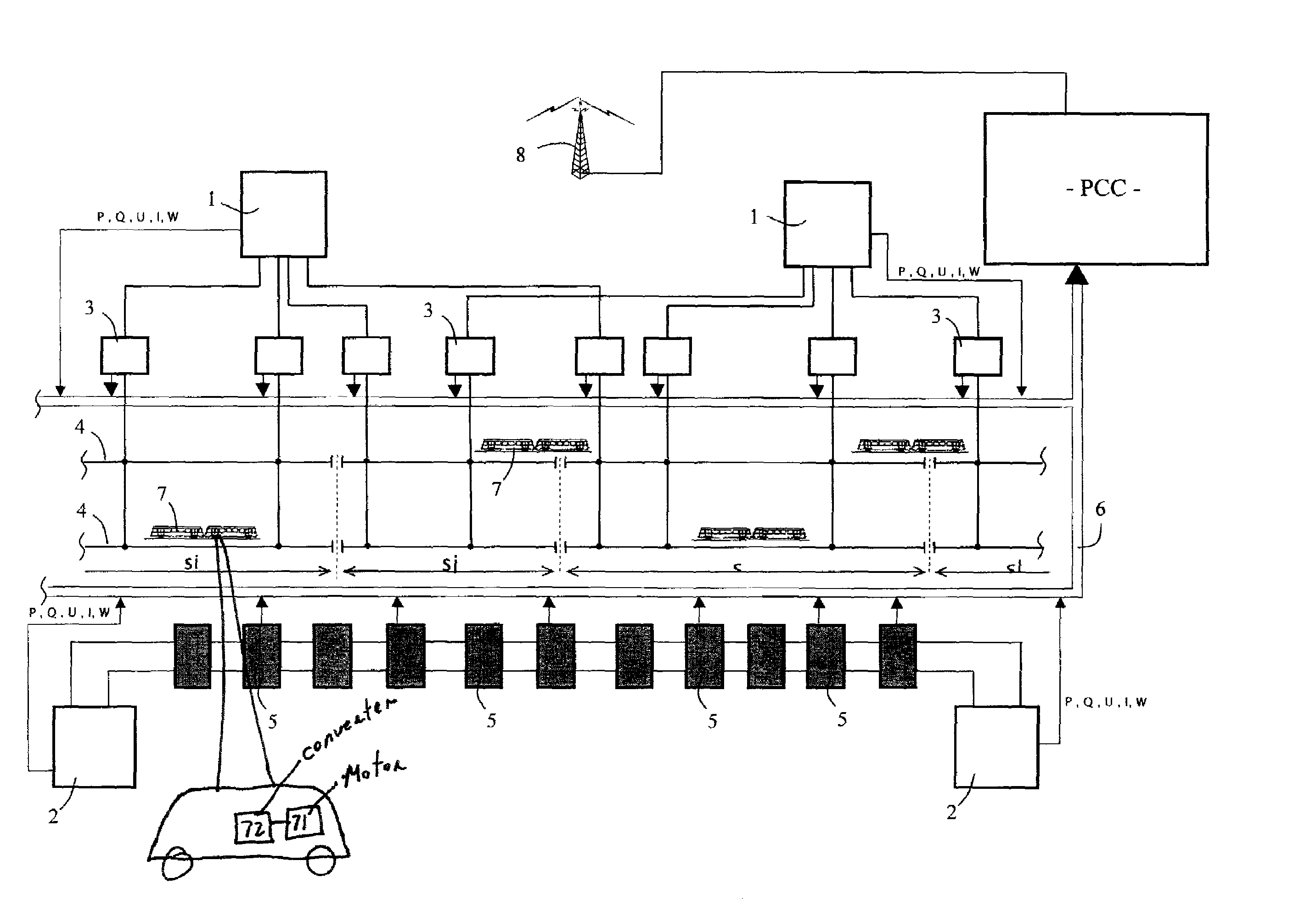
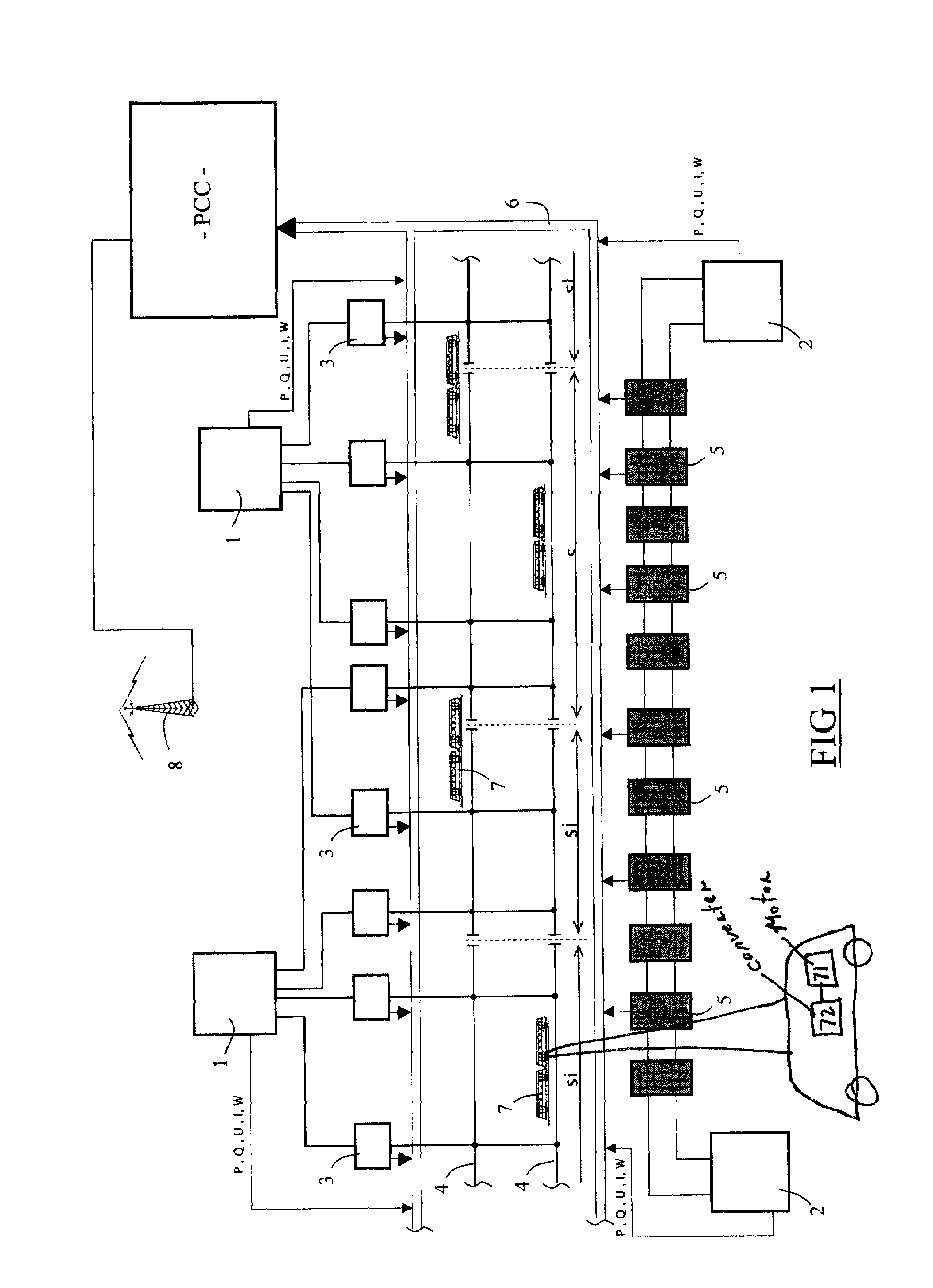
[0031]FIG. 1 is a simplified representation of a power supply system for an underground railway system. The power supply system shown in this figure includes two pairs of high-voltage substations 1 and 2 each supplied with electrical power by power supply lines, not shown in the figures, belonging an external electrical power supply network, such as the EDF network in France. The supply voltage when this kind of electrical power supply network has to satisfy high power demands is typically of the order of 110 kV. The high-voltage substations 1 and 2 each include metering points at which the active power P, the reactive power Q and the wattage W drawn from the external network by the high-voltage substation are measured. The external electrical power supplier uses the res...


PUM


Abstract

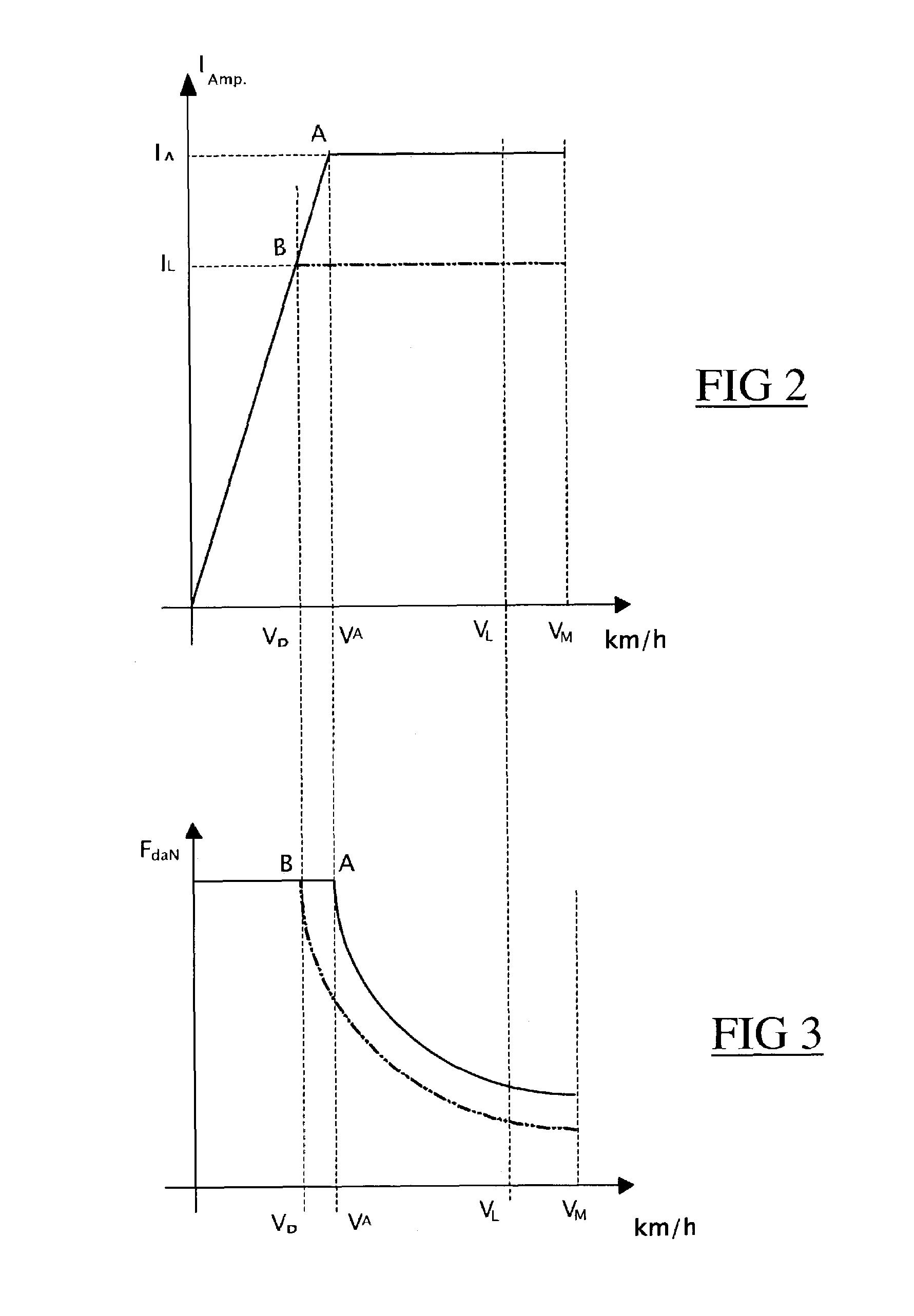
A method of monitoring and regulating the power and the energy consumed by a transport system including electrically propelled vehicles, said transport system including a power supply system including one or more power supply substations connected to an external electrical power supply network, said power supply substation or substations supplying energy to traction substations supplying power to power supply line sections having vehicle-mounted current pick-up means connected thereto, each vehicle carrying a power converter which is supplied with power by said current pick-up means and which monitors the power supplied to a traction motor of said vehicle, which method includes the following steps:measuring the instantaneous electrical power and / or energy drawn from the external electrical power supply network by said power supply substation or substations, andif the power or energy drawn from the external network tends to exceed an assigned threshold, sending one or more vehicles a set point acting on the converter on board said vehicle to reduce temporarily the power and / or the speed of rotation of the traction motor.

Description

[0001]The invention relates to a method and to a system for monitoring and regulating the power and the energy consumed by a transport system using electrically propelled vehicles and whose electrical power requirements are supplied by an external electrical power supply network.BACKGROUND OF THE INVENTION[0002]Transport systems such as underground railway, tram, trolleybus and guided road vehicle systems have high power requirements which are unevenly distributed through the day and essentially consist of the traction power that is dissipated by the vehicles of the system. The power requirements peak in the morning and in the afternoon, at times corresponding to the morning and evening rush hours. It is therefore not advantageous for companies operating these transport systems to acquire their own electrical power stations to supply electrical power, since the power stations would have to be rated to cater for the peak power in the rush hours, and would rarely be operated at their ...

Claims


Application Information

Patent Timeline
Patent Type & Authority Patents(United States)
IPC IPC(8): H02J1/10B60L15/40B60M3/00
CPCB60L9/00B60L11/1803B60L11/1805B60L15/20B60L15/2072B60M3/00B60L2250/10Y02T10/7005Y02T10/92B60L2200/26Y02T10/7275B60L2250/16Y02T10/72B60L50/51B60L50/52Y02T10/64Y02T10/70B60L15/00
Inventor SEDDIKI, RACHIDCORNIC, DANIEL
Owner ALSTOM TRANSPORT TECH SAS
Learn More