
Method and system for removing mercury from combustion gas

a technology of combustion gas and mercury, which is applied in the direction of electrostatic separation, machines/engines, process and machine control, etc., can solve the problems of mercury not being efficiently removed from combustion gas, difficult to obtain uniform distribution of particulate matter within ductwork, and exacerbate the problems of conventional methods

Active Publication Date: 2008-05-20
GENERAL ELECTRIC CO
View PDF21 Cites 7 Cited by
  • Summary
  • Abstract
  • Description
  • Claims
  • Application Information

AI Technical Summary

Benefits of technology

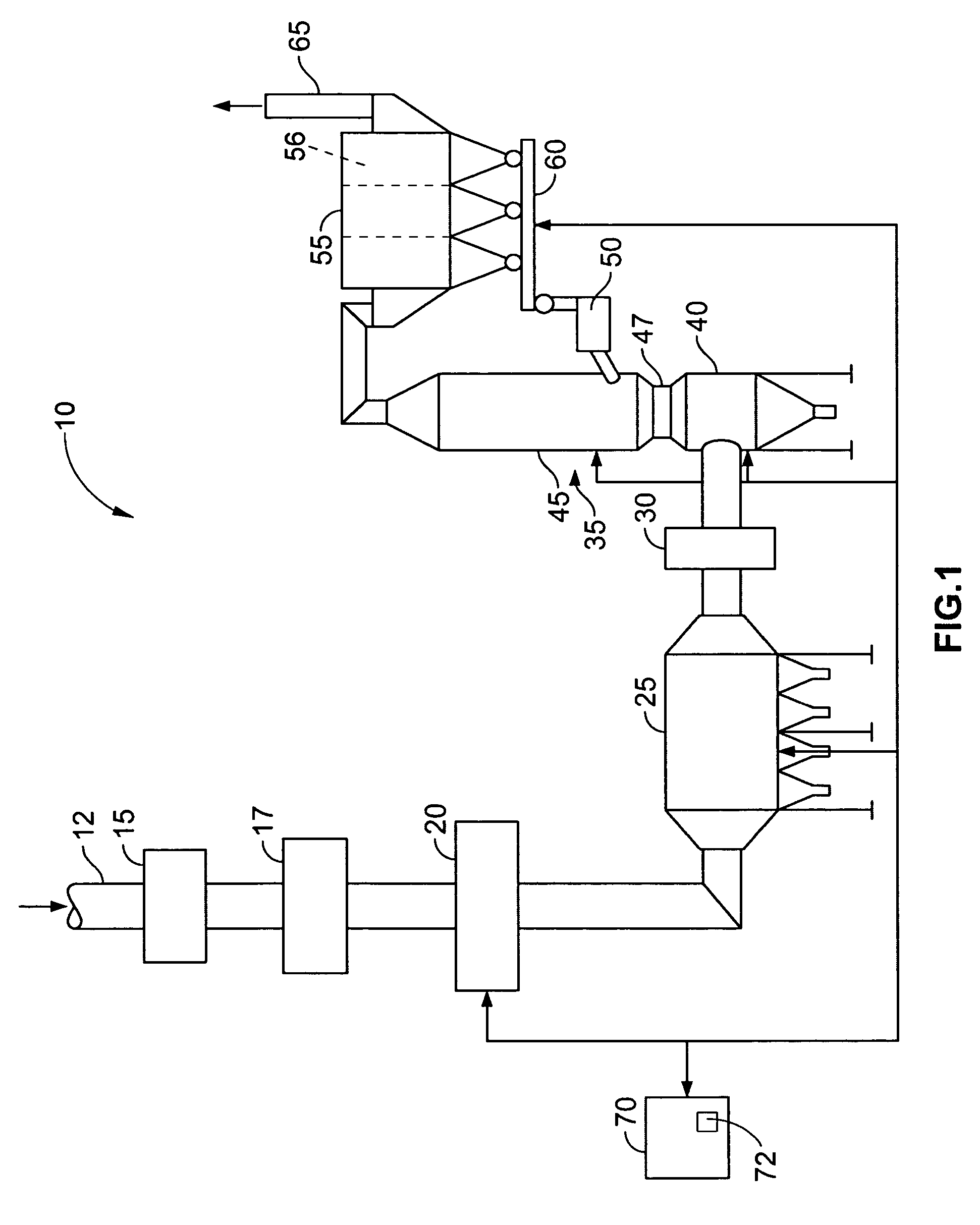
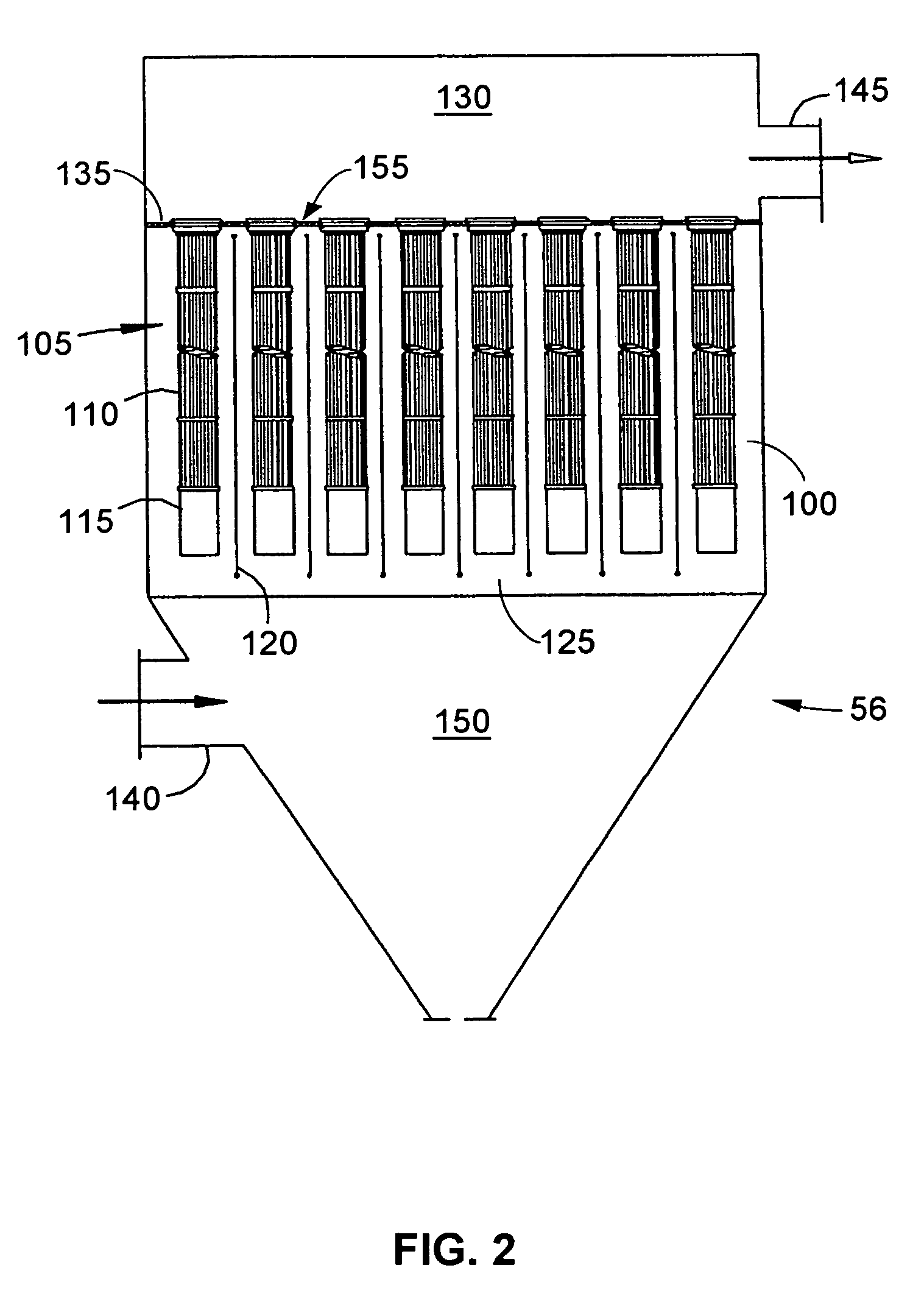
"The present invention provides a method and system for continuously removing mercury from a supply of combustion gas. The method involves adjusting a power input to an electrostatic precipitator to control the amount of fly ash emitted from the precipitator. A turbulent flow of combustion gas is produced to suspend particulate matter containing fly ash, and a substantial portion of the mercury is absorbed within the fly ash. The supply of combustion gas is then filtered to remove the particulate matter and mercury. The control system monitors the emission of fly ash from the precipitator to control the amount of absorption sites available downstream. The system includes an electrostatic precipitator, a cooling device, and a control system that monitors and controls the amount of mercury absorption sites available downstream. The system produces a turbulent flow of combustion gas and removes mercury from the supply in a continuous process."

Problems solved by technology

With such conventional methods, it is difficult to obtain uniform distribution of the particulate matter within the duct work.
As a result of poor mixing and / or carbon fallout, mercury is not efficiently removed from the combustion gas.
In an attempt to solve such problems, an injection rate of activated carbon is increased, which further exacerbates the problems associated with the conventional methods.

Method used


Image

  • Method and system for removing mercury from combustion gas
  • Method and system for removing mercury from combustion gas
  • Method and system for removing mercury from combustion gas

Examples


Embodiment Construction

[0009]The present invention provides a method and system for continuously removing hazardous and / or toxic compounds, such as mercury vapor, from combustion gas produced during a combustion process within a furnace or boiler, for example. Combustion gas having combustion products including, without limitation, carbon monoxide, water, hydrogen, nitrogen and mercury is a direct result of combusting solid and / or liquid fuels. Before the combustion gas can be exhausted into the atmosphere, any toxic combustion products, such as mercury, must be sufficiently removed according to governmental and / or environmental standards and procedures.

[0010]The present invention is described below in reference to its application in connection with and operation of a system for continuously removing mercury from a supply of combustion gas generated during a combustion process. However, it will be obvious to those skilled in the art and guided by the teachings herein provided that the invention is likewis...


PUM

PropertyMeasurementUnit
temperatureaaaaaaaaaa

Abstract

A method for continuously removing mercury from a supply of combustion gas is provided. The method includes adjusting a power input to an electrostatic precipitator to control a quantity of fly ash emitted from the electrostatic precipitator. A turbulent flow of combustion gas is produced to suspend particulate matter including the quantity of fly ash contained in the supply of combustion gas. A substantial portion of the mercury is absorbed within the particulate matter including the quantity of fly ash. The supply of combustion gas is filtered to remove the particulate matter from the mercury. A quantity of absorption sites available for absorbing mercury is controlled by monitoring an emission of fly ash from the electrostatic precipitator.

Description

BACKGROUND OF THE INVENTION[0001]This invention relates generally to a system and method for removing toxic compounds from combustion gases and, more particularly, to a system and method for continuously removing mercury from a supply of combustion gas.[0002]During a typical combustion process within a furnace or boiler, for example, a combustion gas is produced. The combustion gas contains combustion products including, without limitation, carbon monoxide, water, hydrogen, nitrogen and mercury as a direct result of combusting solid and / or liquid fuels. Before the combustion gas can be exhausted into the atmosphere, any hazardous or toxic combustion products, such as mercury, must be sufficiently removed according to governmental and / or environmental standards and procedures.[0003]Conventional methods of removing mercury from combustion gases include injecting activated carbon into the combustion gas as the combustion gas is directed through duct work. With such conventional methods...

Claims


Application Information

Patent Timeline
Patent Type & Authority Patents(United States)
IPC IPC(8): B01D46/00B01D53/64B01J8/00G05D7/00
CPCB01D53/0454B01D53/08B01D53/64B03C3/017B01D2251/404B01D2251/606Y10S423/05B01D2257/602B01D2258/0283B03C2201/32B01D2253/102
Inventor TAYLOR, ROBERT W.LISSIANSKI, VITALI VICTORSEEKER, WILLIAM RANDALL
Owner GENERAL ELECTRIC CO
Learn More