
Method for non-contact cleaning of a surface

a non-contact surface and cleaning technology, applied in the field of cleaning surfaces, can solve the problems of surface and possibly subsurface damage, difficult to control the cleaning process, and the complexity of the icp device, etc., and achieve the effects of improving the process, high controllability, and rapid shaping of hard-to-machine materials

Inactive Publication Date: 2008-05-13
IMREAL ENTERPRISES
View PDF118 Cites 7 Cited by
  • Summary
  • Abstract
  • Description
  • Claims
  • Application Information

AI Technical Summary

Benefits of technology

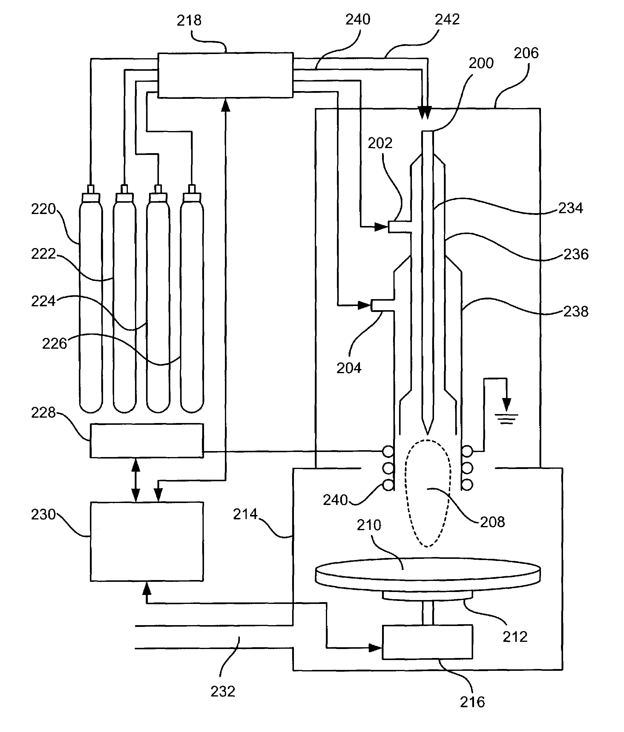
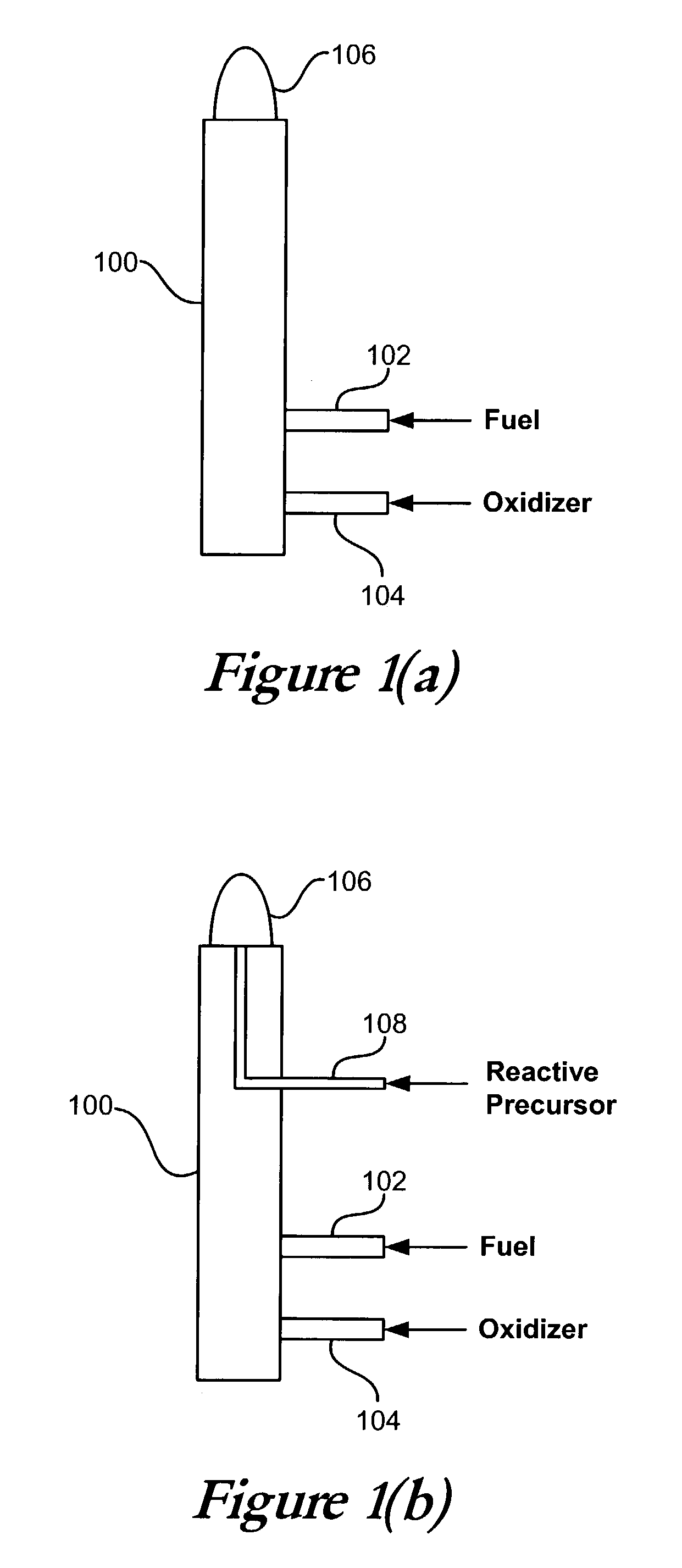
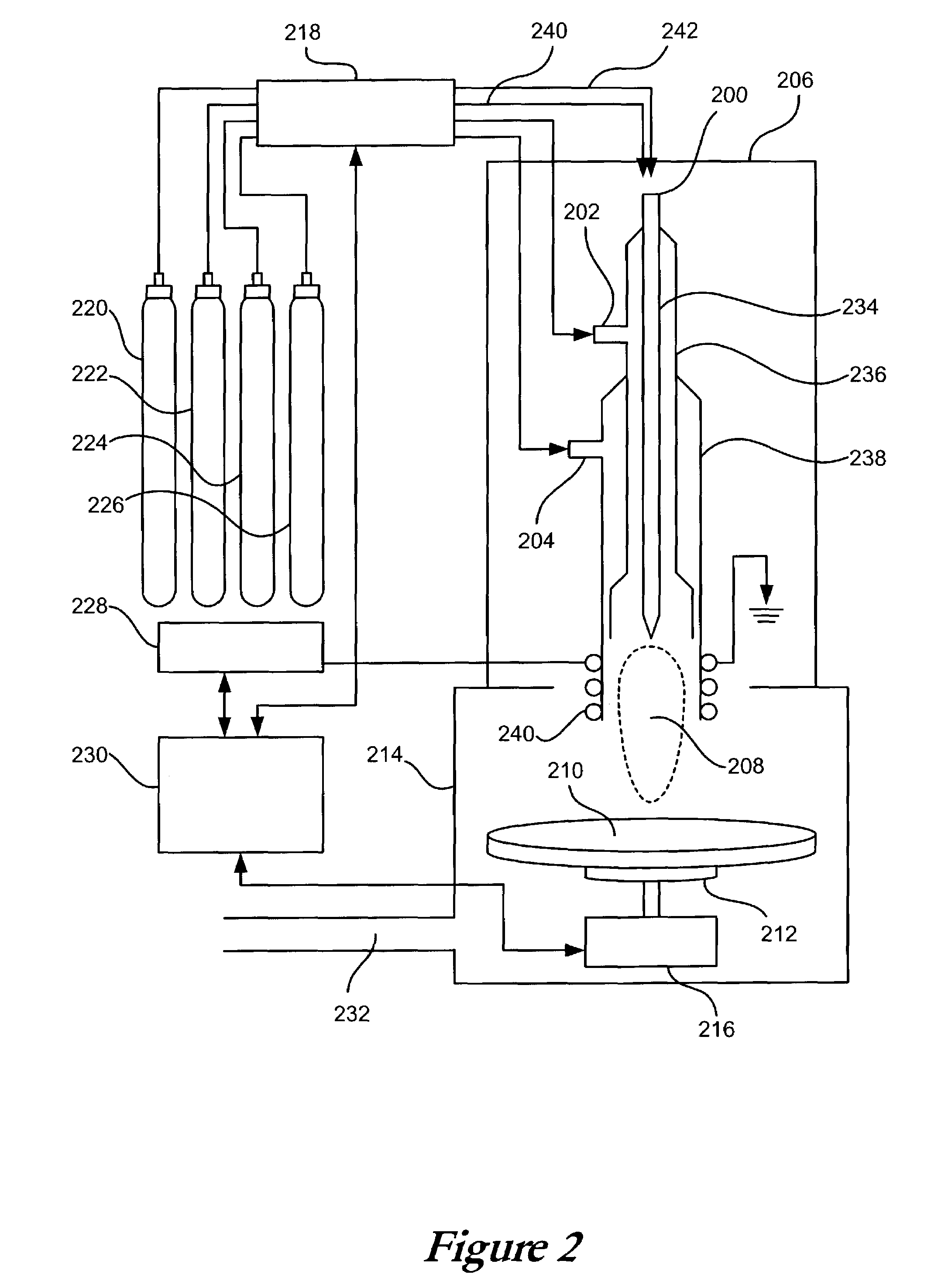
[0006]Systems and methods in accordance with embodiments of the present invention can overcome deficiencies and obstacles in the prior art to produce a highly-controllable, precise, atmospheric, non-contact surface cleaning process. These systems and methods also provide improved processes for cleaning and rapidly shaping hard-to-machine materials using a single or multiple flame torch.

Problems solved by technology

Modern materials present a number of formidable challenges to the fabricators of a wide range of optical, semiconductor, and electronic components, many of which require precision shaping, smoothing, and polishing.
Further, such a component often requires the cleaning of at least one surface before or after a step in the fabrication process.
Many current physical contact methods have the disadvantage of involving mechanical force at the microscopic scale that creates surface and possibly subsurface damage.
An ICP device can be quite complex, however, and comes with certain limitations.
An ICP device can also be relatively expensive, and may not always be an optimal system for cleaning materials from a surface.
The need for a vacuum chamber increases cost and reduces throughput.
RIE methods are not directional, and therefore cannot be used to simply clean a specific area of contamination from a wafer.

Method used


Image

  • Method for non-contact cleaning of a surface
  • Method for non-contact cleaning of a surface
  • Method for non-contact cleaning of a surface

Examples


Embodiment Construction

[0013]When developing systems useful for reactive atom plasma (RAP) processing, it was determined that certain parts needed to be cleaned before being processed. As used herein, “cleaning” refers to the selective removal of contaminants from a surface. A contaminant on the surface of a workpiece during an etch or surface modification process can act as a mask, causing the material below the contaminant to remain unaffected. This masking phenomenon can result in the formation of a plateau with the contaminant at the top. Alternately, the contaminant can act as a catalyst, causing the contaminant particles to burrow into the surface, with each particle potentially creating a pit in the surface. Either result is highly undesirable.

[0014]Initially, all the parts to be processed were cleaned manually in a class 100 clean room using wipes and solvents. While reasonably successful, the approach left behind a small number of particles, and, more problematically, a thin layer of organic mate...


PUM

PropertyMeasurementUnit
inner diameteraaaaaaaaaa
temperatureaaaaaaaaaa
mass flowaaaaaaaaaa

Abstract

A flame torch can be used to clean the surface of a contact-sensitive object, such as a glass optic, extremely thin workpiece, or semiconductor wafer by providing a reactive precursor gas to the feed gases of the torch. Reactive atom plasma processing can be used to clean the surface of a contaminant that chemically combines with the atomic radicals of the precursor without affecting the surface. The torch can also be used to modify the surface after cleaning, without transferring the object or engaging in any intermediate processing, by supplying a second reactive precursor that reacts with the surface itself. The flame torch can be used to shape, polish, etch, planarize, deposit, chemically modify and / or redistribute material on the surface of the object.This description is not intended to be a complete description of, or limit the scope of, the invention. Other features, aspects, and objects of the invention can be obtained from a review of the specification, the figures, and the claims.

Description

FIELD OF INVENTION[0001]The field of the invention relates to cleaning of surfaces using a flame and reactive gases.BACKGROUND[0002]Modern materials present a number of formidable challenges to the fabricators of a wide range of optical, semiconductor, and electronic components, many of which require precision shaping, smoothing, and polishing. Further, such a component often requires the cleaning of at least one surface before or after a step in the fabrication process. Other components simply require a fine cleaning separate from the fabrication process. Many current physical contact methods have the disadvantage of involving mechanical force at the microscopic scale that creates surface and possibly subsurface damage.[0003]The basic designs and structure of a flame torch are well known, one of which contains a central tube that introduces a gas, liquid, or solid into the flame. This is the technology of flame photometry, a method by which a material can be chemically analyzed by ...

Claims


Application Information

Patent Timeline
Patent Type & Authority Patents(United States)
IPC IPC(8): B23K9/00B08B7/00C03C23/00G03F1/82H01L21/00H01L21/306H01L21/3065H05H1/30
CPCB08B7/0035C03C23/007C03C23/0075G03F1/82H01L21/02046H01L21/3065H01L21/67028H05H1/30B23K10/00C23G3/00C23G5/00
Inventor CARR, JEFFREY W.
Owner IMREAL ENTERPRISES
Learn More