
Prosthetic valve with pores

a technology of prosthesis and pores, applied in the field of medical devices, can solve the problems of loss of effectiveness, physical manifestation and pathology, and the insufficientness of venous valves, and achieve the effect of reducing the risk of vascular valve rupture, reducing the effectiveness of vascular valves, and improving the quality of vascular valves

Active Publication Date: 2008-04-22
COOK MEDICAL TECH LLC
View PDF31 Cites 82 Cited by
  • Summary
  • Abstract
  • Description
  • Claims
  • Application Information

AI Technical Summary

Benefits of technology

The present invention provides valves for implantation in body vessels and other suitable environments. The valves have a leaflet that can move between first and second positions to control fluid flow. The leaflet has a plurality of pores and is attached to a support frame that can be compressed and expanded. The valves can be made using a method that involves attaching the leaflet to the support frame so that it is moveable between first and second positions. The valves can be used to control fluid flow in body vessels and have the advantage of being able to prevent fluid flow in the opposite direction.

Problems solved by technology

Varying fluid pressures over time, however, can introduce a reverse flow direction in the vessel.
While natural valves may function for an extended time, some may lose effectiveness, which can lead to physical manifestations and pathology.
For example, venous valves are susceptible to becoming insufficient due to one or more of a variety of factors.
Over time, the vessel wall may stretch, affecting the ability of the valve leaflets to close.
Furthermore, the leaflets may become damaged, such as by formation of thrombus and scar tissue, which may also affect the ability of the valve leaflets to close.
Once valves are damaged, venous valve insufficiency may be present, which may lead to discomfort and possibly ulcers in the legs and ankles.

Method used


Image

  • Prosthetic valve with pores
  • Prosthetic valve with pores
  • Prosthetic valve with pores

Examples


Embodiment Construction

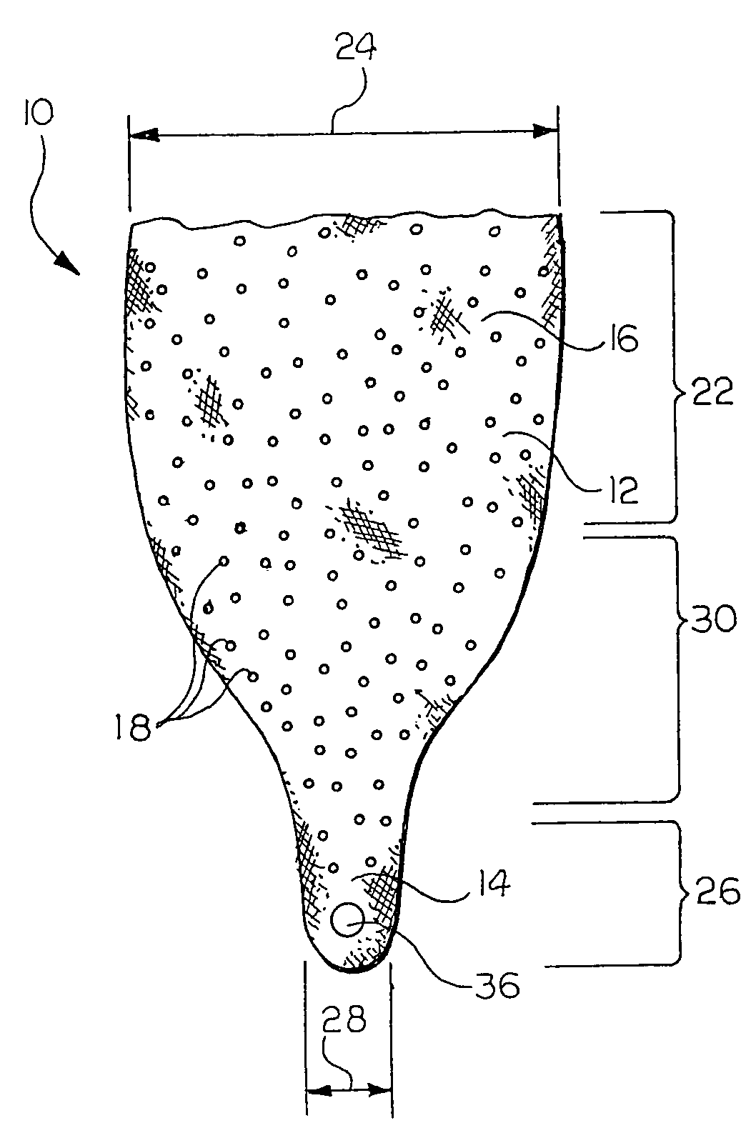
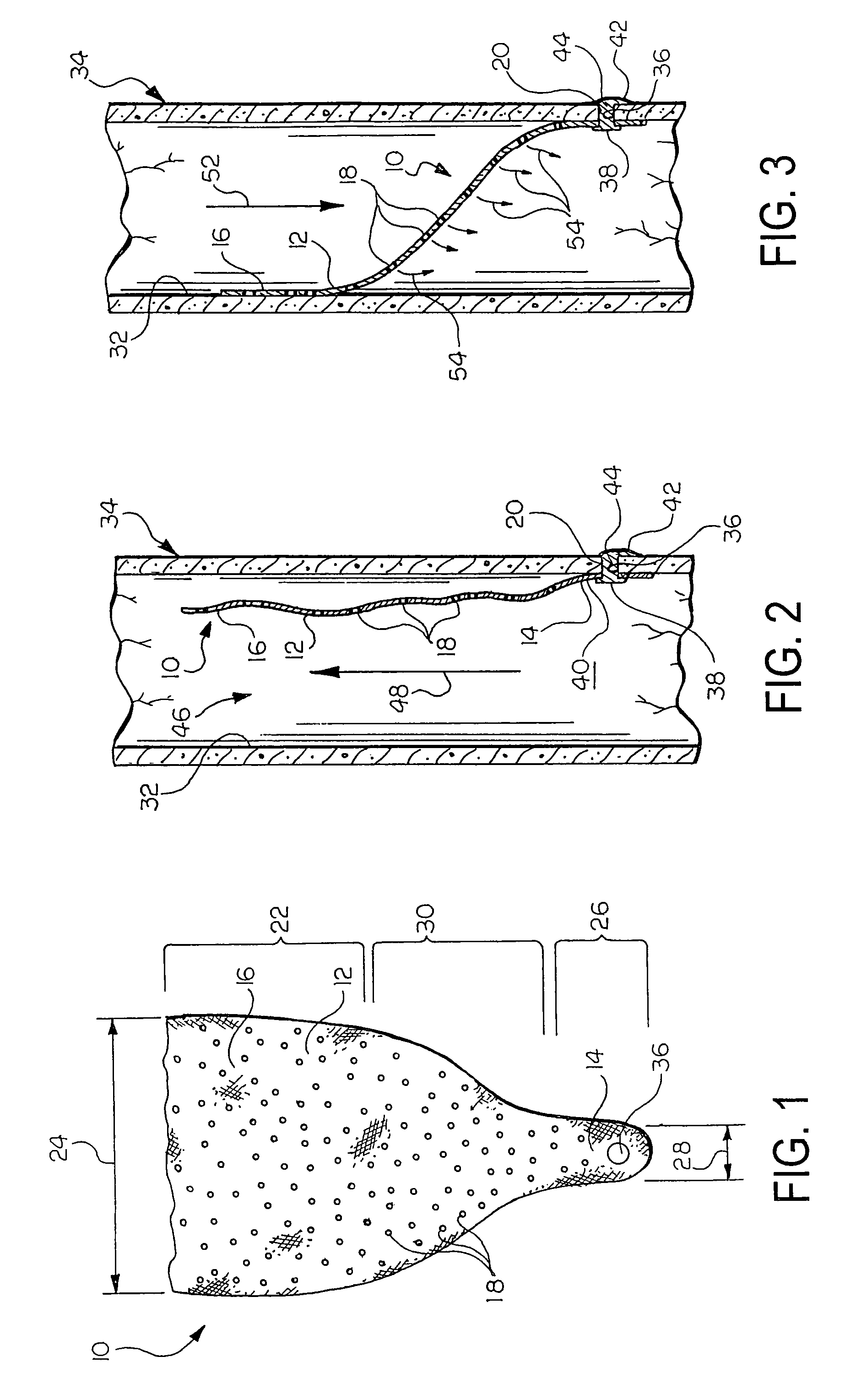
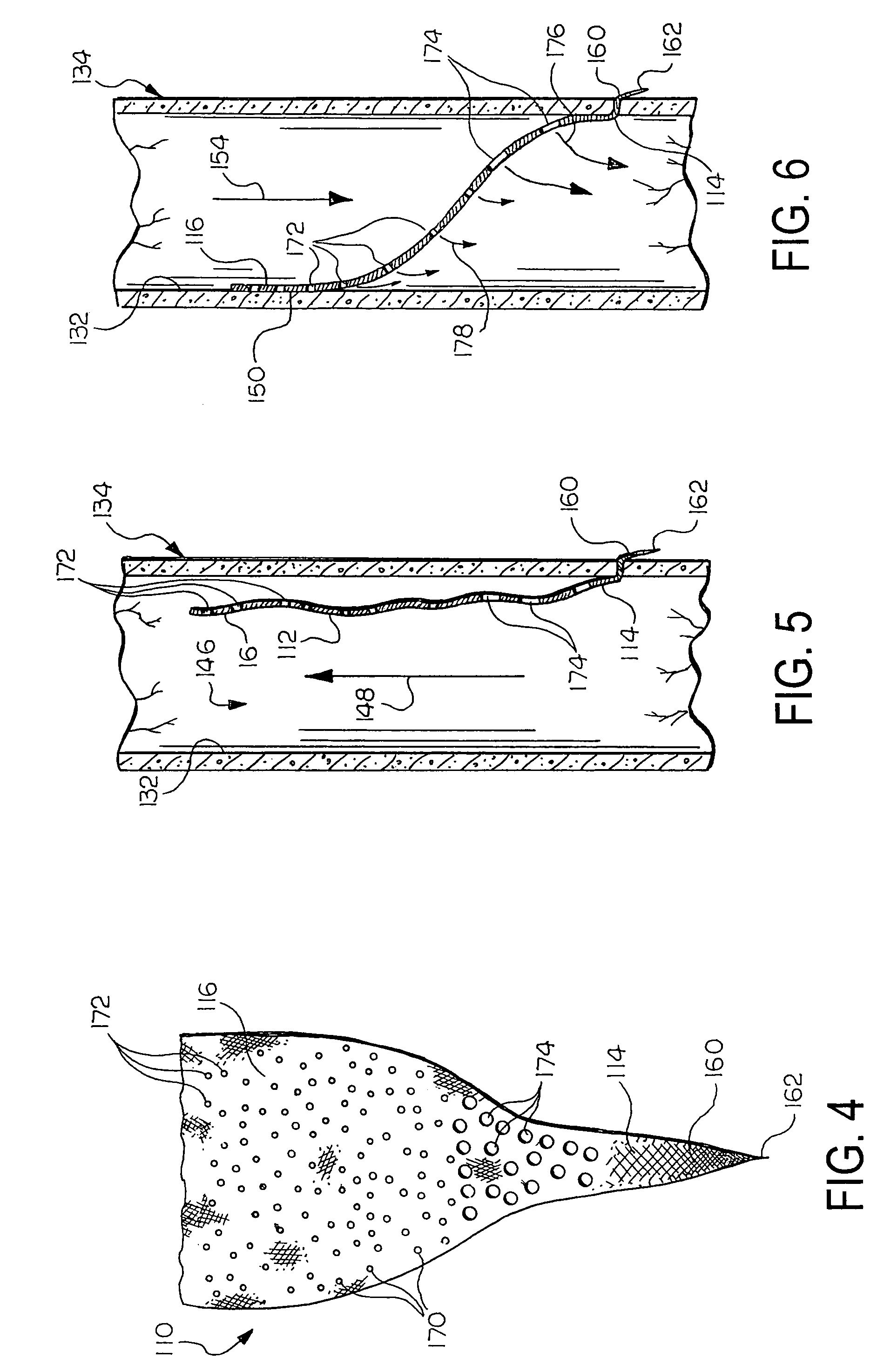
[0009]The present invention provides valves for implantation in body vessels and other suitable environments. In one exemplary embodiment, a valve comprises a leaflet that has a valve portion that is moveable between first and second positions. In the first position, the leaflet permits fluid flow in a first direction through a body vessel in which the valve is implanted. In the second position, the leaflet substantially prevents fluid flow through the body vessel in a second, opposite direction. The leaflet defines a plurality of pores, and the valve includes a means for maintaining an axial position of the leaflet in the body vessel in which the valve is implanted.

[0010]In another exemplary embodiment, a valve comprises a support frame having radially compressed and radially expanded configurations. The valve includes at least one leaflet attached to the support frame that defines a plurality of pores. At least a portion of the at least one leaflet is moveable between first and se...


PUM


Abstract

Prosthetic valves for regulating fluid flow are provided. The valves have at least one leaflet that includes a plurality of pores that allow a quantity of retrograde flow to pass through the leaflet when the valve is in a closed configuration.

Description

CROSS REFERENCE TO RELATED APPLICATION[0001]This application claims priority to U.S. Provisional Application Ser. No. 60 / 608,605 filed on Sep. 10, 2004, the disclosure of which is hereby incorporated into this disclosure in its entirety.FIELD OF THE INVENTION[0002]The present invention relates to medical devices. More particularly, the invention relates to intraluminal valve prostheses.BACKGROUND OF THE INVENTION[0003]Many vessels in animal bodies transport fluids from one bodily location to another. Frequently, fluid flows in a unidirectional manner along the length of the vessel. Varying fluid pressures over time, however, can introduce a reverse flow direction in the vessel. In some vessels, such as mammalian veins, natural valves are positioned along the length of the vessel and act as one-way check valves that open to permit the flow of fluid in the desired direction and close to prevent fluid flow in a reverse direction, i.e., retrograde flow. The valves can change from an ope...

Claims


Application Information

Patent Timeline
Patent Type & Authority Patents(United States)
IPC IPC(8): A61F2/06A61F2/04
CPCA61F2/2412A61F2/2418A61F2/2475A61F2/04A61F2230/0095A61F2220/0016A61F2220/0058A61F2230/0026
Inventor CASE, BRIAN C.KIRTS, BETH ANNOSBORNE, THOMAS A.
Owner COOK MEDICAL TECH LLC
Learn More