
Tilt steering column device for vehicle

a technology for tilting steering column and vehicle, which is applied to steering columns, steering parts, vehicle components, etc., can solve the problems of large number of roller members, requiring an unnecessary and laborious operation, and laborious to fit plate-like spacer members, so as to improve the built-in property, improve the sliding effect, and improve the sliding

Active Publication Date: 2008-04-08
NSK LTD
View PDF28 Cites 8 Cited by
  • Summary
  • Abstract
  • Description
  • Claims
  • Application Information

AI Technical Summary

Benefits of technology

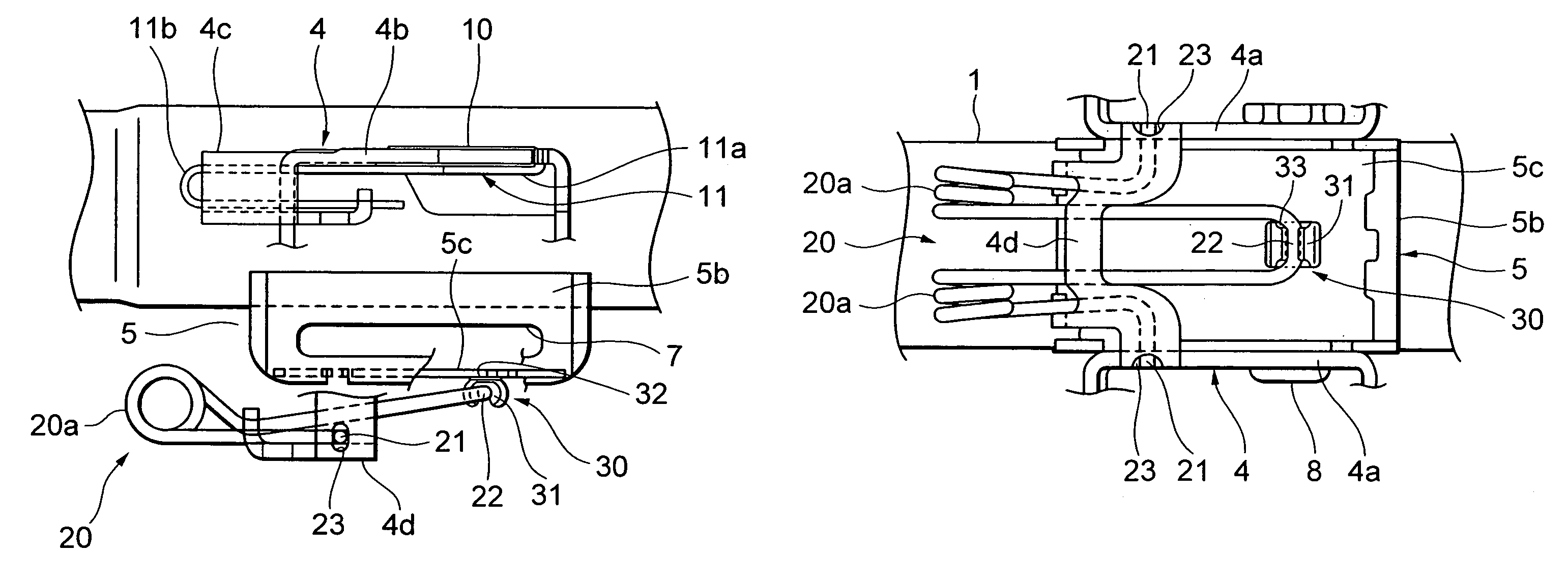
The present invention provides a tilt and / or telescopic type steering column apparatus for a vehicle that facilitates assembly and achieves both a highly preferable mute level of noises caused when adjusting in a tilt and / or telescopic position and a highly preferable slidability. The improvement includes a balance or leap-up spring attached to the steering column or column sided bracket, and a slide member attached to the other biasing end portion of the balance or leap-up spring. The slide member is formed of a synthetic resin and includes an accommodation holding portion and an abutting portion that can be easily built in and prevents noises and improves slidability. The built-in property of the slide member is improved, and the cost is decreased.

Problems solved by technology

In this case, however, it is laborious to fit the plate-like spacer member.
In this case, an operation of assembling in the fastening bolt must involve intruding the fasting bolt into the tube, thus requiring an unnecessary and laborious operation on the occasion of the assembly.
In this case, however, a couple of pulley-like roller members are needed, and the number of roller members becomes large.
Further, the roller members are constructed rotatably, and hence a working accuracy gets important, and an operation of guiding and fitting the other biasing end portion into a groove of the pulley-like roller member is laborious.

Method used


Image

  • Tilt steering column device for vehicle
  • Tilt steering column device for vehicle
  • Tilt steering column device for vehicle

Examples


Embodiment Construction

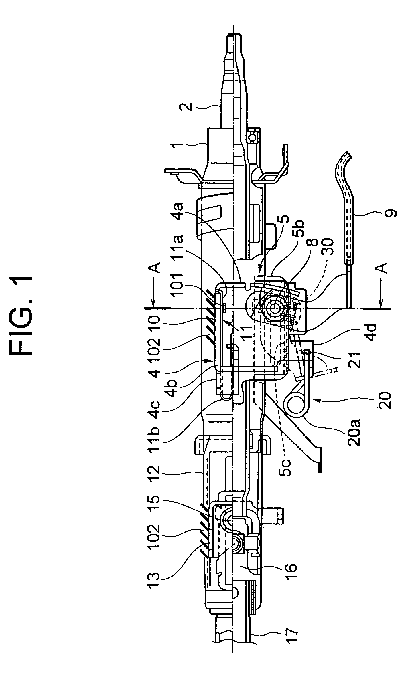
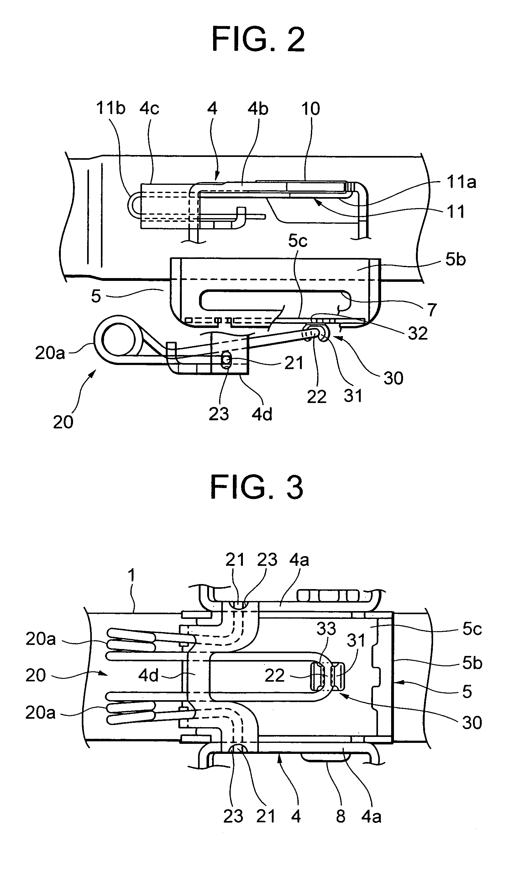
[0022]An impact absorbing type and tilt and / or telescopic type steering column apparatus according to an embodiment of the present invention, will hereinafter be described with reference to the drawings.

[0023]As shown in FIG. 1, a steering shaft 2 is rotatably supported within a steering column 1. A steering wheel (unillustrated) is secured to an upper side end of the steering shaft 2.

[0024]The steering column 1 is fixedly supported onto a car body at two portions, i.e., an upper bracket provided on a rear side of the vehicle and a lower bracket provided on a front side thereof.

[0025]The upper bracket on the rear side of the vehicle is constructed of a car body sided upper bracket 4 (tilt bracket) fixed to the car body, and of a column sided upper bracket 5 (distance bracket in FIG. 2) fixed to the steering column 1, wherein the two upper brackets 4 and 5 are press-fitted to each other.

[0026]The car body sided upper bracket 4 includes U-shaped body sided plate portions 4a, 4a extend...


PUM


Abstract

In a tilt and / or telescopic type steering column apparatus for a vehicle, in which a column sided bracket attached to a steering column is so provided as to be swingable about a car body sided bracket attached to a car body, the two brackets are press-fitted to each other by fastening a fastening bolt inserted through the two brackets and thus fastened in a tilt and / or telescopic adjustment position, while a tilt and / or telescopic adjustment can be made by releasing the two brackets from being press-fitted by slackening the fastening bolt, a balance or leap-up spring for biasing a pair of biasing end portions each other is provided, the one biasing end portion of the balance or leap-up spring is fitted to the car body or the car body sided bracket, and the other biasing end portion supports sad steering column or the column sided bracket, an improvement is characterized in that a slide member abutting on the steering column or the column sided bracket is attached to the other biasing end portion of the balance or leap-up spring.

Description

TECHNICAL FIELD[0001]The present invention relates to a tilt type steering column apparatus for a vehicle.BACKGROUND ARTS[0002]For example, in a tilt and / or telescopic type steering column apparatus for a vehicle, a steering column is so constructed as to be tiltable and / or telescopically slidable, and, when fastened in a tilt and / or telescopic adjustment position, a column sided bracket (distance bracket) attached to the steering column is held in a way that press-fits this bracket to a car body sided bracket (tilt bracket) attached to a car body by use of a clamp mechanism.[0003]A balance spring for sustaining a steering column so as to raise the steering column in order to prevent the steering column from carelessly coming off when performing a tilt and / or telescopic adjustment. This balance spring includes, for instance, a pair of biasing end portions giving a bias in such directions that they expand each other. One biasing end portion is attached to the car body or the car body...

Claims


Application Information

Patent Timeline
Patent Type & Authority Patents(United States)
IPC IPC(8): B62D1/18B62D1/184B62D1/187
CPCB62D1/184B62D1/187
Inventor ISHIDA, RYUUICHIYOSHIMOTO, SHINTOMARU, MASAKI
Owner NSK LTD
Learn More