
Phase adjusting apparatus, phase adjusting method for use therein, and program for phase adjusting method

a phase adjustment and apparatus technology, applied in the field of phase adjustment apparatus and phase adjustment method, can solve the problems of complex and large scale circuit required for performing the process, and the required circuit is more complex and larger in scal

Inactive Publication Date: 2008-03-25
NEC CORP
View PDF6 Cites 4 Cited by
  • Summary
  • Abstract
  • Description
  • Claims
  • Application Information

AI Technical Summary

Benefits of technology

[0017]It is therefore an object of the present invention to provide a phase adjusting apparatus, a phase adjusting method for use therein, and a program for such a phase adjusting method, which are capable of adjusting phases without involving an increase in circuit scale and without depending on the generation of pointer stuff in SDH.
[0024]In transmitting data with a virtual concatenation made up of a plurality of VC-3 or VC-4 channels that provide a single bandwidth, the phase adjusting apparatus according to the present invention can absorb a differential delay caused due to path length differences without depending on the generation of pointer stuff.

Problems solved by technology

However, the above conventional phase adjusting process is problematic in that the circuit required for performing the process is complex and large in scale because it is necessary to determine, at all times, whether data of each of the VC-3 channels is stored in the phase adjustment memory or not based on the write and read addresses, and when data of all the VC-3 channels of the virtual concatenation are stored, the stored data need to be read.
Therefore, as the number of multiplexed VC-3 / VC-4 channels and storage areas (addresses) are larger, the required circuit is more complex and larger in scale.

Method used


Image

  • Phase adjusting apparatus, phase adjusting method for use therein, and program for phase adjusting method
  • Phase adjusting apparatus, phase adjusting method for use therein, and program for phase adjusting method
  • Phase adjusting apparatus, phase adjusting method for use therein, and program for phase adjusting method

Examples


Embodiment Construction

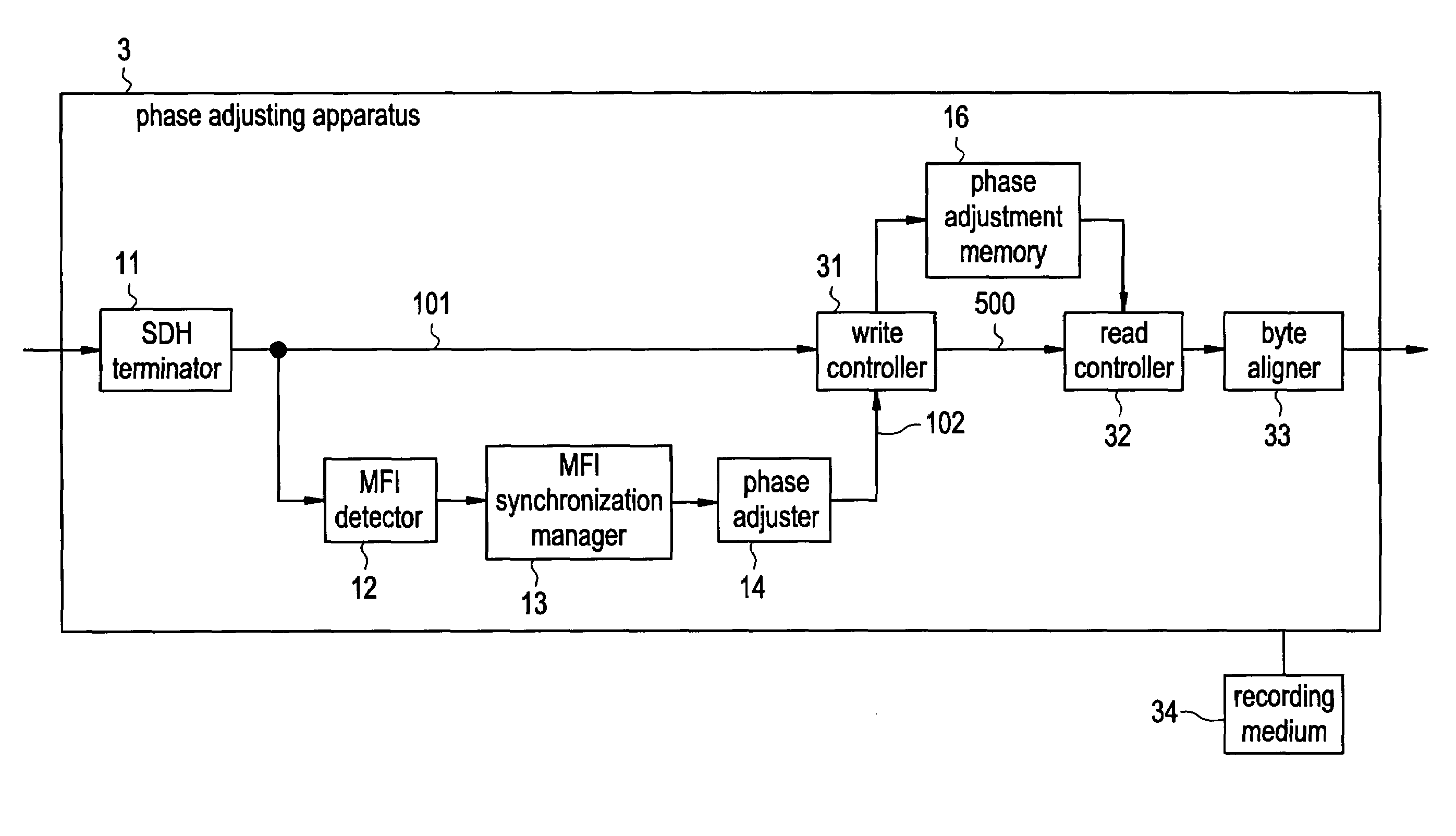
[0045]FIG. 4 shows in block form phase adjusting apparatus 1 according to an embodiment of the present invention. As shown in FIG. 4, phase adjusting apparatus 1 comprises SDH (Synchronous Digital Hierarchy) terminator 11, MFI ((Multi-Frame Indicator) detector 12, MFI synchronization manager 13, phase adjuster 14, write controller 15, phase adjustment memory 16, write frame manager 17, read controller 18, and recording medium 19.

[0046]SDH terminator 11 detects the leading end of a frame from received data and detects the leading ends of multiplexed VC-3 frames from pointer information in order to detect MFI information for managing a chronological sequence of VC (Virtual Container)-3 channels that make up a virtual concatenation.

[0047]MFI detector 12 detects MFI values from H4 bytes at fixed positions from the leading end information of the multiplexed VC-3 channels. MFI synchronization manager 13 determines the continuity of the detected MFI values to manage the synchronization of ...


PUM

PropertyMeasurementUnit
phaseaaaaaaaaaa
MFIaaaaaaaaaa
lengthsaaaaaaaaaa

Abstract

An MFI synchronization manager determines the continuity of MFI values to manage the synchronization of the MFI values. A phase adjuster detects a reference VC-3 channel of VC-3 channels which make up a virtual concatenation based on detected MFI values. A write controller writes frame data into a phase adjustment memory based on a write permission signal from the phase adjuster and data valid / invalid information. A write frame manager manages the frame data written in the phase adjustment memory with respect to each of the VC-3 channels and generates a read permission signal for the frame data whose all VC-3 channels of the concatenation have been written. A read controller reads the frame data from phase adjustment memory according to the read permission signal.

Description

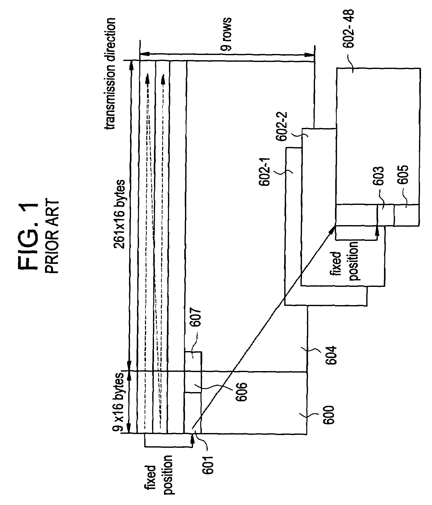
BACKGROUND OF THE INVENTION[0001]1. Field of the Invention[0002]The present invention relates to a phase adjusting apparatus, a phase adjusting method for use therein, and a program for such a phase adjusting method, and more particularly to a phase adjusting method for absorbing a differential delay without depending on the pointer stuff in a virtual concatenation of a plurality of VC (Virtual Container)-3 channels of a signal which is made up of multiplexed VC-3 channels.[0003]2. Description of the Related Art[0004]The frame format of an STM (Synchronous Transfer Mode)-16 frame which is made up of multiplexed 48 VC-3 channels is illustrated in FIG. 1 of the accompanying drawings. As shown in FIG. 1, the STM-16 frame comprises section overhead (SOH) 600 for transferring data of a monitoring control system, payload 604, and area 601 for storing pointer information representative of leading ends of multiplexed VC-3 channels.[0005]Payload 604 comprises multiplexed 48 VC-3 channels 602...

Claims


Application Information

Patent Timeline
Patent Type & Authority Patents(United States)
IPC IPC(8): H04J3/06G11B7/0045H04J3/00H04J3/14H04L7/00H04L12/24
CPCH04J3/0623
Inventor HAYASHI, TAKEO
Owner NEC CORP
Learn More