Increased effective aperture for receive arrays

a technology of receiving arrays and effective apertures, applied in the direction of sonic/ultrasonic/infrasonic transmission, mechanical vibration separation, electrical apparatus, etc., can solve the problems of inability to achieve, large apertures, and limited sonar dome performance in determining the location of acoustic targets, so as to improve the effective speed of sound and enhance the effect of sonar receiving arrays

Inactive Publication Date: 2008-03-25
THE UNITED STATES OF AMERICA AS REPRESENTED BY THE SECRETARY OF THE NAVY
View PDF4 Cites 1 Cited by
  • Summary
  • Abstract
  • Description
  • Claims
  • Application Information

AI Technical Summary

Benefits of technology

[0012]Another object of this invention is to provide enhanced sonar receive arrays within a sonar dome by reducing an effective speed of sound within the dome.
[0013]Still another object of this invention is to provide enhanced sonar receive arrays within a sonar dome by introducing a small amount of bubbles that will effectively reduce sound speed within the dome.
[0014]In accordance with one aspect of this invention, there is provided a sonar dome having at least a receive array housed therein. A plurality of independently generated bubbles are formed within the fluid of the sonar dome, the generated bubbles being of an amount and size to reduce the speed of sound within the dome relative to an absence of the generated bubbles and thereby increase an effective aperture of the receive array. Typically, each individual bubble is less than 0.01 mm in diameter. The generated bubbles should be sized to remain stable over a long period of time, enable a constant speed of sound within the fluid, and have a large resonance frequency in comparison to the bandwidth of interest.

Problems solved by technology

The performance of sonar domes in determining the location of acoustic targets is limited in size by spacing of the receiver elements in an array.
Often times, a larger aperture is necessary, and cannot be achieved due to physical limitations caused by the current sonar dome size.
The following patents, for example, disclose known sonar domes and reduction of cavitation, but do not disclose a solution to the need to increase the effective aperture of sonar receive arrays that are enclosed in a sonar dome.

Method used


Image

  • Increased effective aperture for receive arrays
  • Increased effective aperture for receive arrays
  • Increased effective aperture for receive arrays

Examples


Embodiment Construction

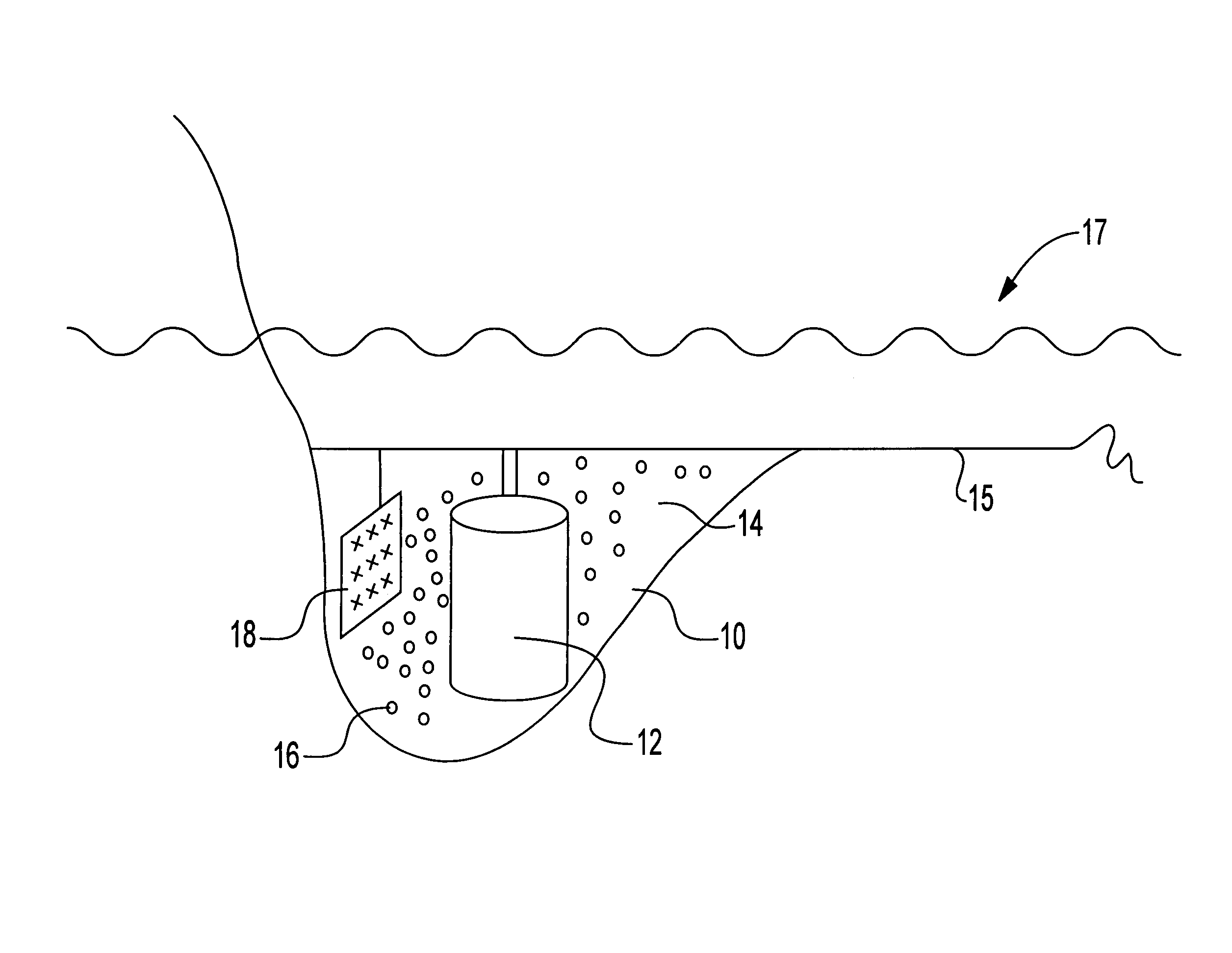
[0019]The present invention is explained in connection with the sonar dome shown generally at element 10 in the FIG. 1. Other components of the sonar dome 10 relative to explanation of the invention include a receive array 12 and a fluid medium 14 housed within the sonar dome 10. The fluid medium 14 is typically environmental seawater since the sonar dome 10 under consideration is used in the active or passive underwater detection of ocean targets (not shown). Other fluid media can be used within the scope of this invention. It will be understood that the sonar dome 10 is in fact of the type that is mounted to a ship's or submarine's hull 15 under a surface 17 of water and will contain all the necessary elements to function to that end, although these additional components will not be described herein as they are not pertinent to the subject matter of the invention.

[0020]The premise of the present invention is that the introduction of a very small quantity of bubbles 16 can signific...


PUM


Abstract

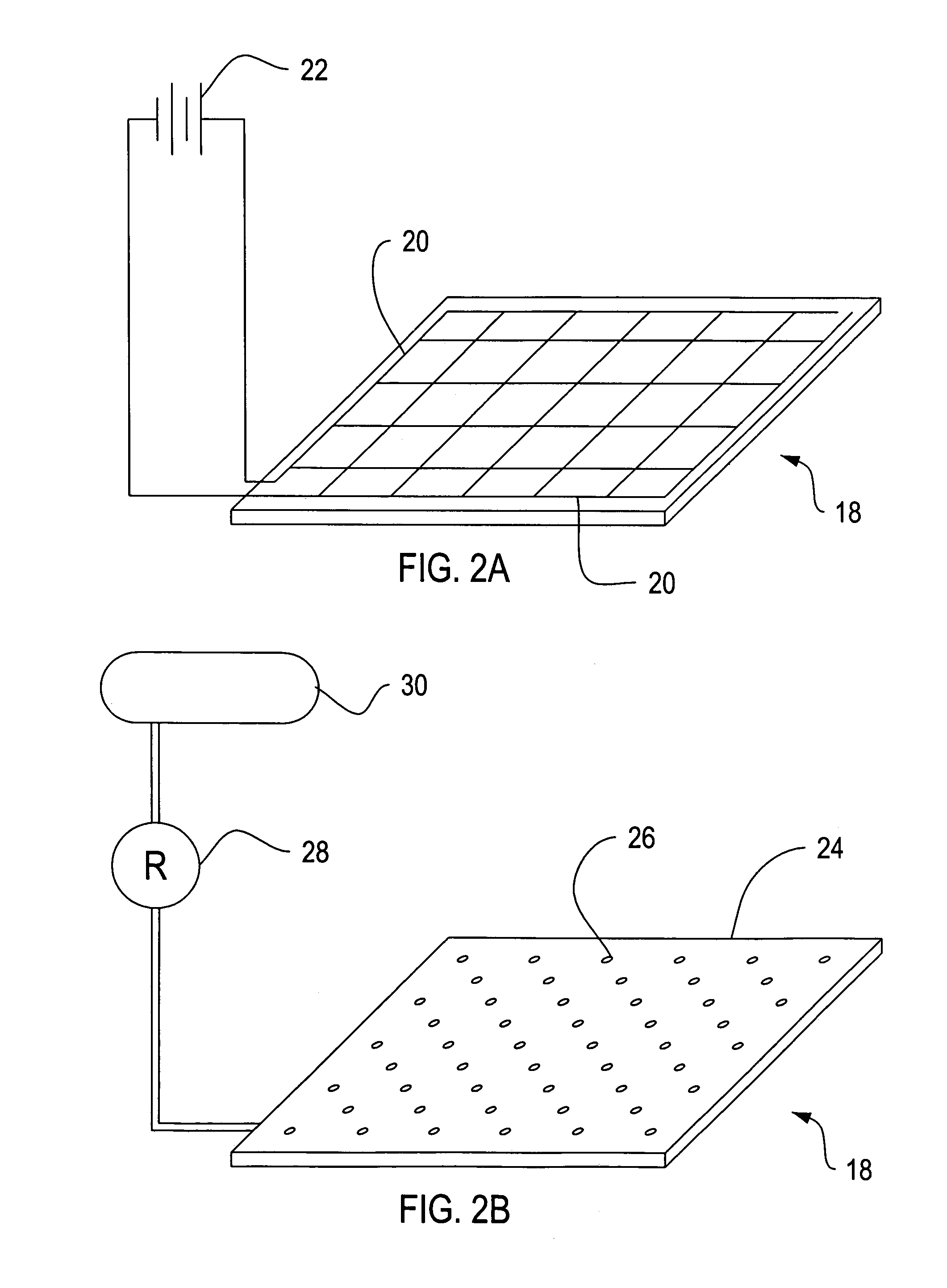
A sonar dome having an acoustic array housed therein. A plurality of bubbles are generated within the fluid inside the sonar dome. The generated bubbles are of an amount and size to reduce the speed of sound within the sonar dome fluid. Reduction of the speed of sound within the sonar dome fluid effectively increases the aperture of the acoustic array. The bubbles can be generated from a gas source or electrolytically. Typically, each individual bubble is less than 0.01 mm in diameter to reduce bubble velocity in the fluid.

Description

STATEMENT OF GOVERNMENT INTEREST[0001]The invention described herein may be manufactured and used by or for the Government of the United States of America for governmental purposes without the payment of any royalties thereon or therefor.BACKGROUND OF THE INVENTION[0002](1) Field of the Invention[0003]This invention generally relates to enhancing receive arrays in a sonar dome.[0004](2) Description of the Prior Art[0005]The current art for sonar domes is such that the sonar domes containing receive arrays are typically pressurized with sea water. The performance of sonar domes in determining the location of acoustic targets is limited in size by spacing of the receiver elements in an array. In one part, this is a function of the Nyquist-Shannon sampling theorem as applied spatially to an array of sensors. Beam width is a function of the array spacing and the speed of sound in the media. Often times, a larger aperture is necessary, and cannot be achieved due to physical limitations c...

Claims


Application Information

Patent Timeline
Patent Type & Authority Patents(United States)
IPC IPC(8): H04B11/00
CPCH04B11/00
Inventor RUFFA, ANTHONY A.
Owner THE UNITED STATES OF AMERICA AS REPRESENTED BY THE SECRETARY OF THE NAVY
Why Eureka
Try Eureka