Bone fixture apparatus and jig
a technology of fixture and jig, which is applied in the field of bone fixture apparatus, can solve the problems of limited usefulness of these devices, and achieve the effect of accurate positioning of incisions and boring positions
- Summary
- Abstract
- Description
- Claims
- Application Information
AI Technical Summary
Benefits of technology
Problems solved by technology
Method used
Image

Examples
first embodiment
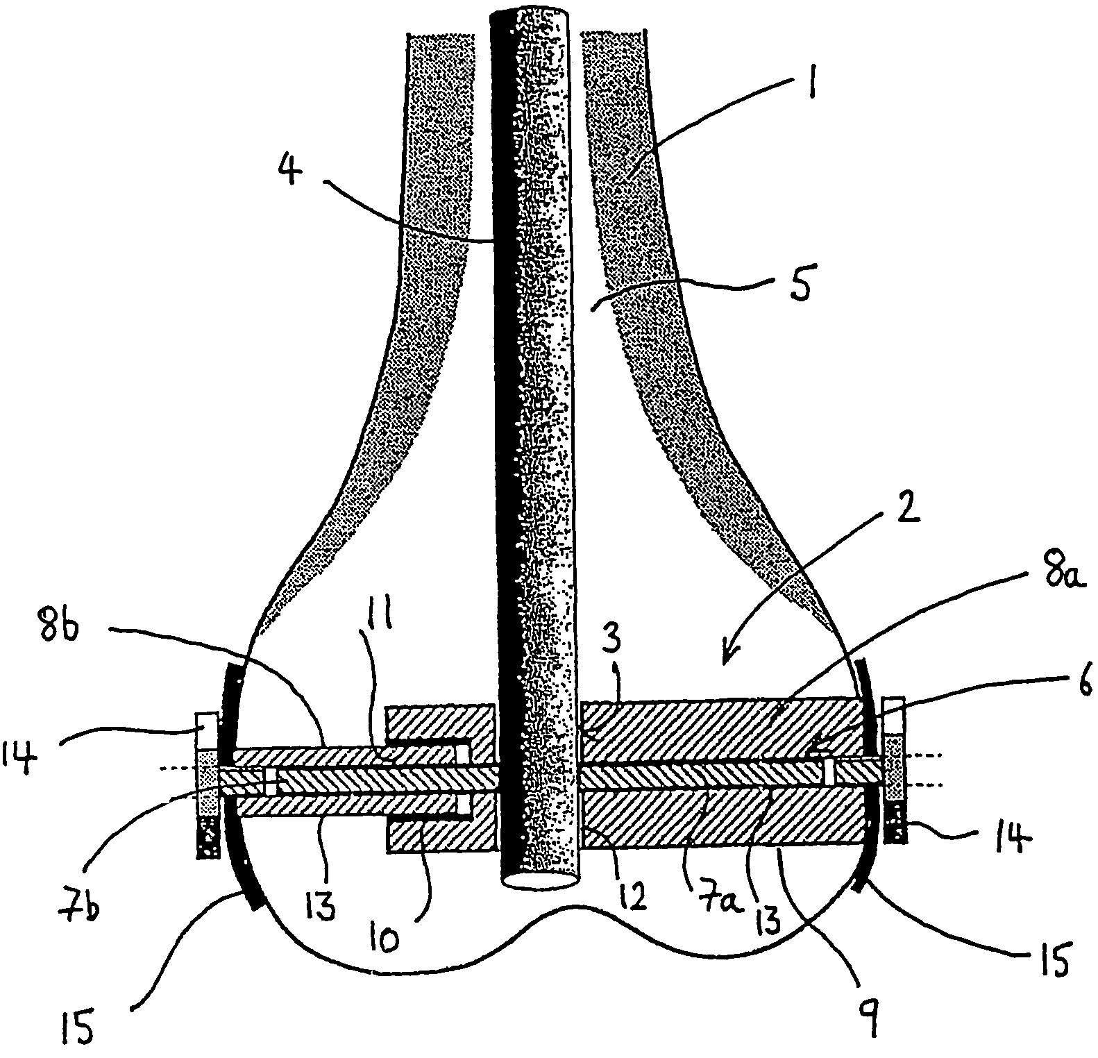
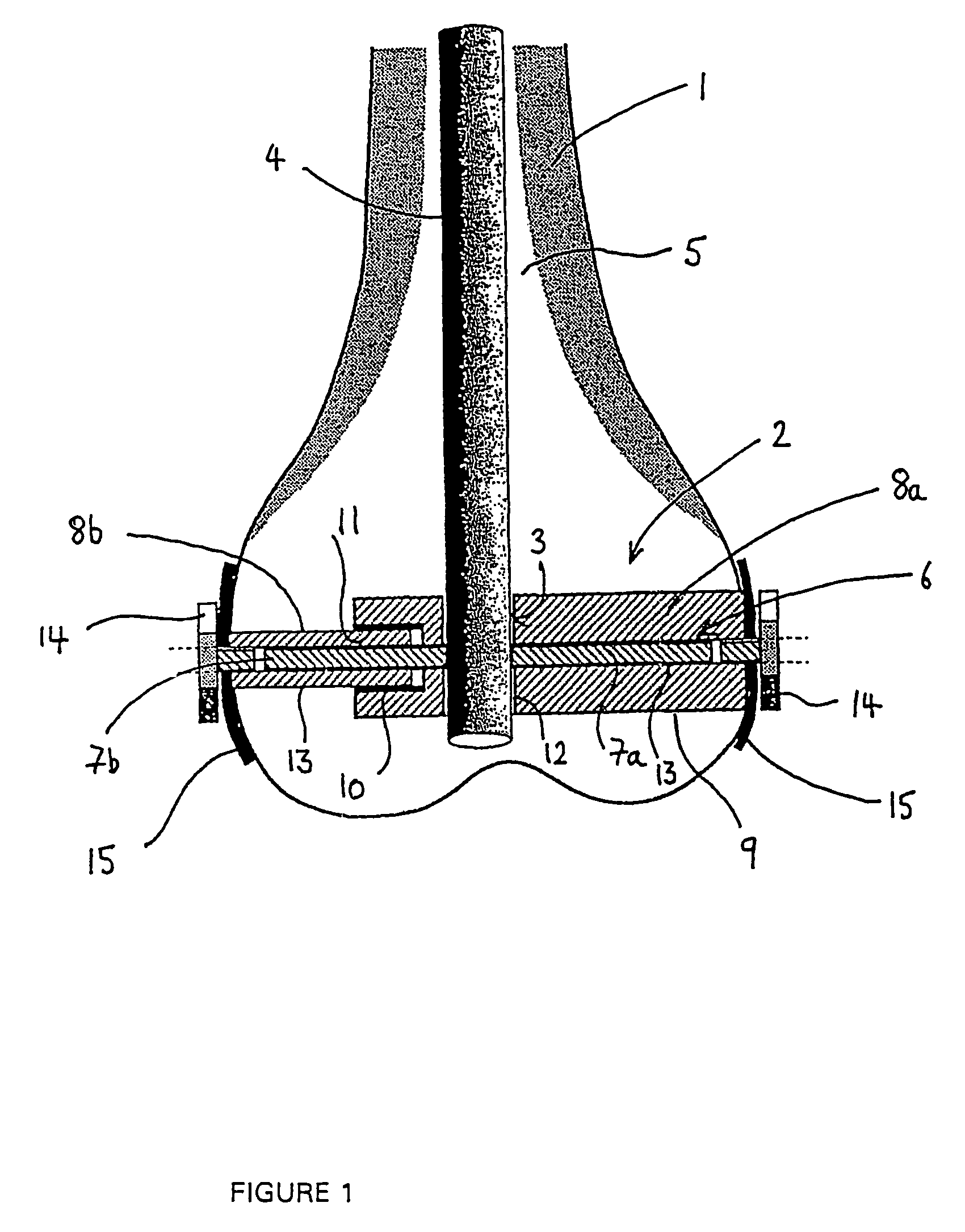
[0019]Referring to FIG. 1, there is shown a bone fixture apparatus in accordance with the invention, as applied to a metaphyseal region of a long bone 1. The apparatus of this embodiment comprises an elongate fixture device, indicated at 2, intended to be inserted generally transversely of the direction of the medullary cavity of the bone 1. The fixture device 2 includes an aperture 3 extending laterally thereof and intended to accommodate an intramedullary nail 4 inserted longitudinally therethrough into the medullary cavity 5 of the bone 1, and the fixture device 2 is further formed with an axial aperture 6 intended to receive a securing element 7 capable of insertion therein to firmly engage the nail 4 with the fixture means 2.
[0020]The fixture device in this embodiment comprises a bolt-like, member 8 intended for insertion into a pre-drilled-passage 9 in the bone 1 and to engage with cancellous bone to provide a secure fixture which assists in stabilising a fracture and provides...
second embodiment
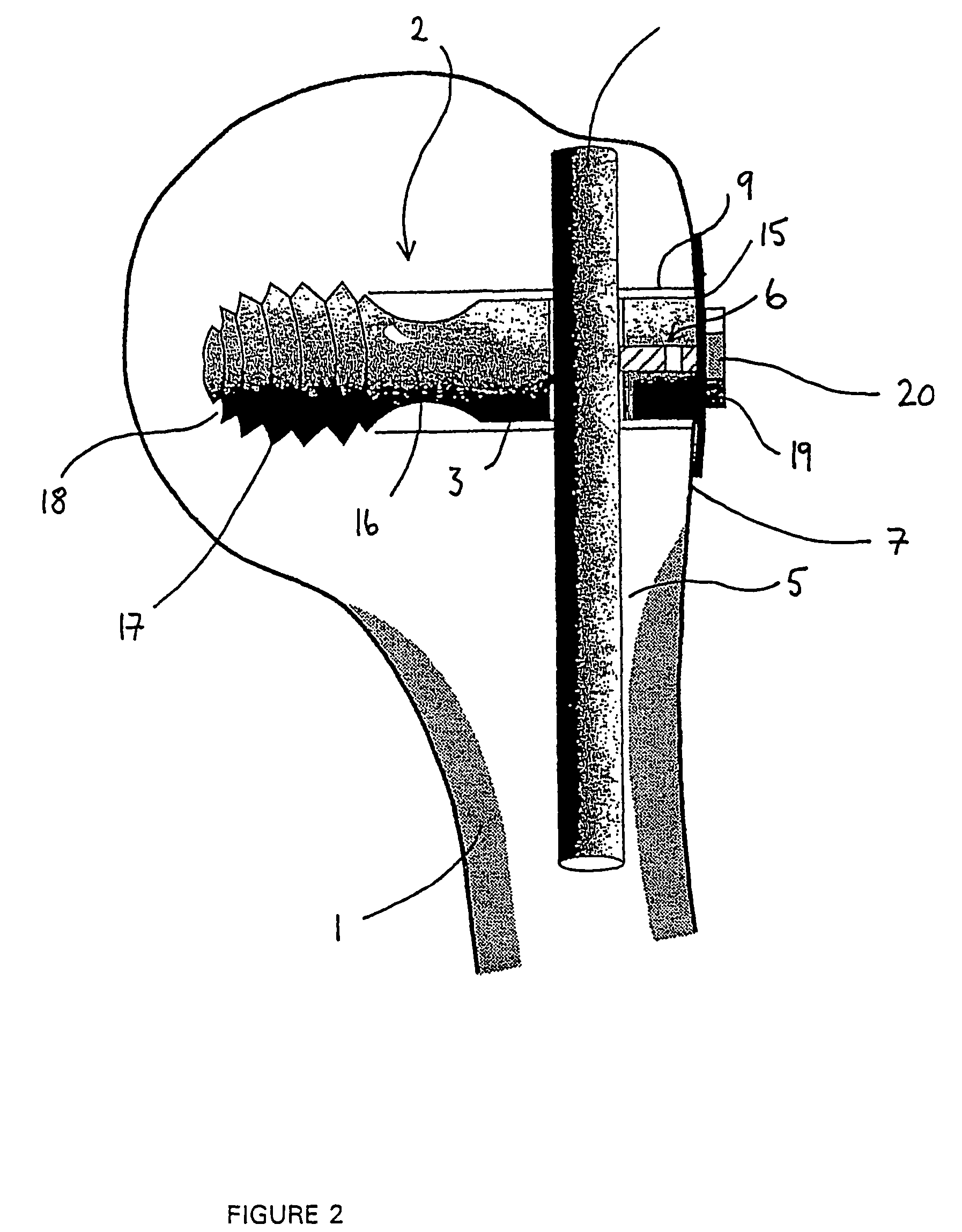
[0027]Referring now to FIG. 2, there is shown the invention, in which the fixture device 2 comprises a screw-like member 16, for example a lag screw, inserted from only one side of the bone but otherwise with generally the same disposition, with respect to the bone, as the bolt-like device 8 described with reference to FIG. 1. In this embodiment, it is essential for the screw-like component 16 to engage, with its screw-threaded distal end 17, into cancellous bone 18 in order to provide a firm fixture base. As with the embodiment of the invention described with reference to FIG. 1, the screw-like member 16 is formed with a nail-receiving aperture 3, extending transversely of its longitudinal axis, through which an intramedullary nail 4 can be inserted. The nail 4 can be firmly secured to the screw-like member 16, as described with reference to FIG. 1, by means of a locking device, such as a grub screw 7, inserted into a suitable bore 6 running axially of the screw-like member 16.
[002...
third embodiment
[0029]Referring now to FIG. 3, the invention will be described, in which the fixture device 2 comprises a finned, nail-like member 21, the finned, and sharpened distal end 22 of which is intended to be embedded, by conventional means, in cancellous bone 18. The remaining features of the nail-like member 21 are similar to those of the screw-like member 16 described with reference to FIG. 2, and will thus not be further described herein.
[0030]In order to accurately locate the fixture device 2 of any of the foregoing embodiments of the invention in relation to the bone to which they are to be affixed, it is preferable to utilize a jig arrangement of the kind to be described with reference to the following FIGS. 4 to 10.
[0031]A common element of the preferred jig arrangements now to be described is the use of a preliminary intramedullary device 23, which will hereinafter be referred to as a probe since it is intended to enter, temporarily and for alignment purposes, into the intramedull...
PUM
 Abstract
Description
Claims
Application Information
 - R&D
- Intellectual Property
- Life Sciences
- Materials
- Tech Scout
- Unparalleled Data Quality
- Higher Quality Content
- 60% Fewer Hallucinations
Browse by: Latest US Patents, China's latest patents, Technical Efficacy Thesaurus, Application Domain, Technology Topic, Popular Technical Reports.
© 2025 PatSnap. All rights reserved.Legal|Privacy policy|Modern Slavery Act Transparency Statement|Sitemap|About US| Contact US: help@patsnap.com