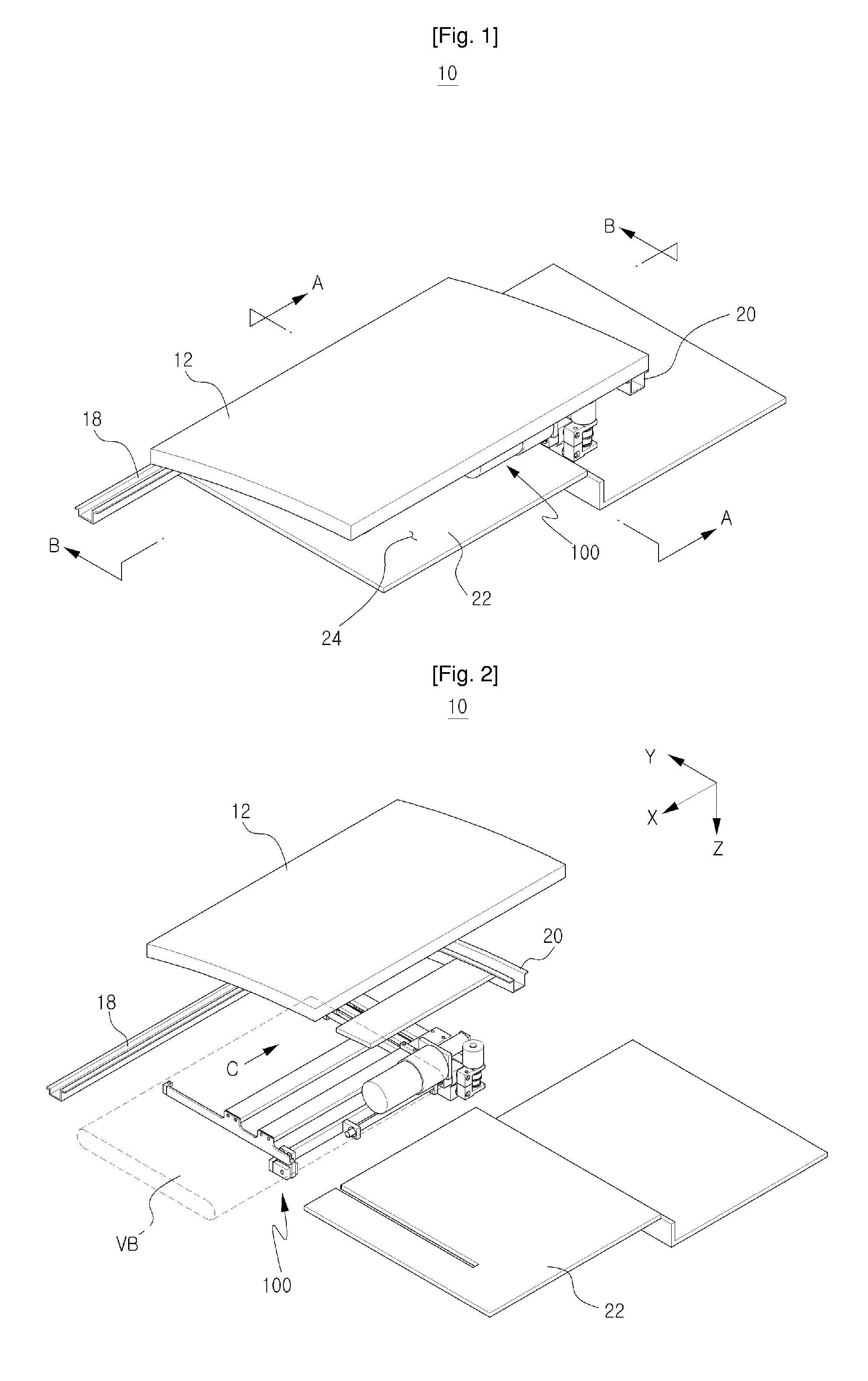
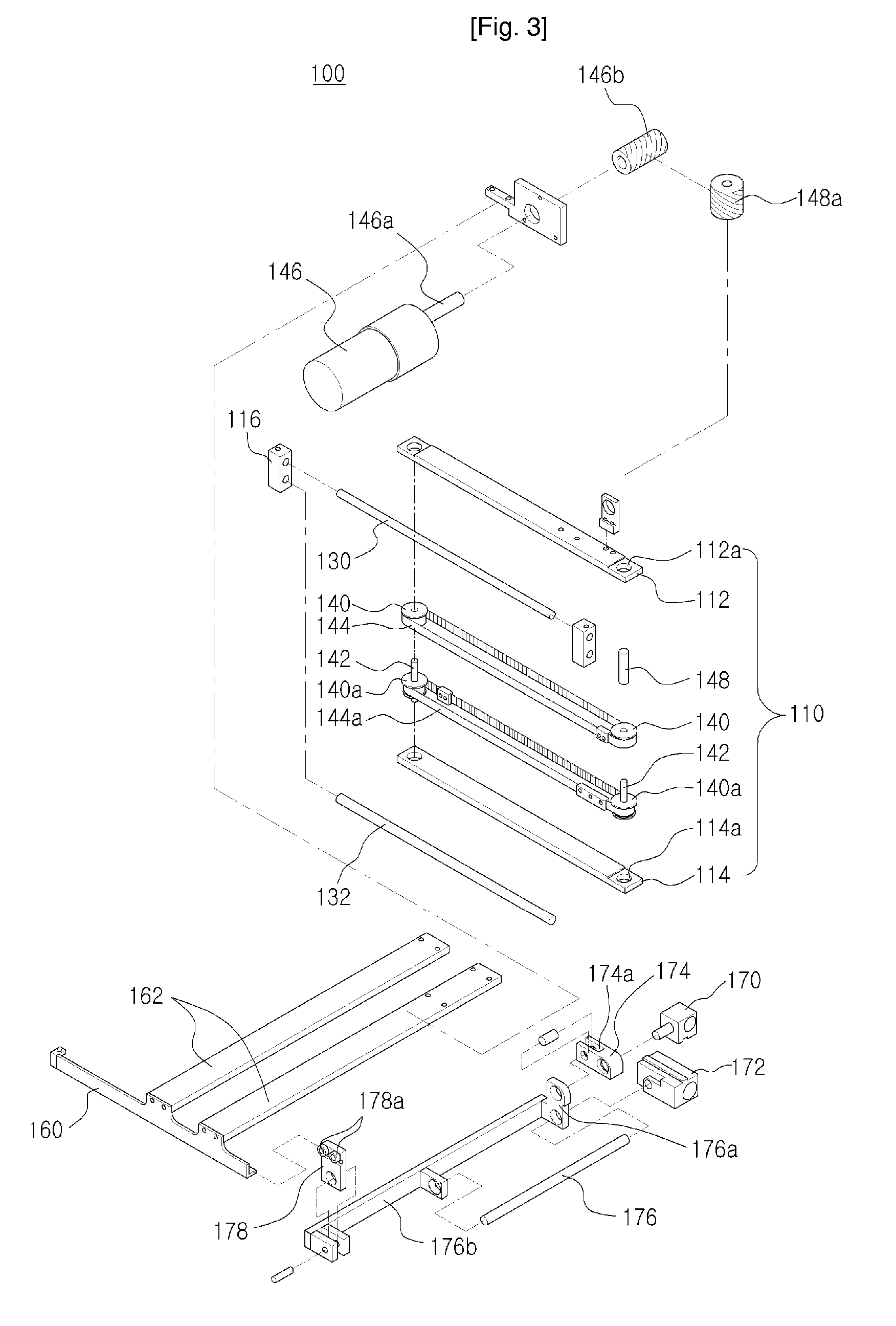
Electromotive sunvisor assembly of a vehicle and the method thereof
a technology of electric sunvisor and assembly method, which is applied in the direction of roofs, transportation and packaging, and investigating phase/state change, etc., can solve the problems of interrupting the driver's view, the sunvisor cannot be adjusted at an angle as much as the driver, and the conventional sunvisor cannot protect passengers from bright sunlight or light sources
- Summary
- Abstract
- Description
- Claims
- Application Information
AI Technical Summary
Benefits of technology
Problems solved by technology
Method used
Image
Examples
second embodiment
[0085]FIG. 14 shows the electromotive sunvisor assembly for vehicles according to the present invention. FIG. 15 shows the state in which the visor body has moved forward. A recess (120a) is formed at one side surface of the main body (120), as shown, and a first rack gear (122) and a second rack gear (122a) are longitudinally formed at the recess (120a) in parallel to each other. A first gear box (124) with a plurality of gears embedded is positioned on the top surface of the upper travel member (170), a first drive gear (124a) connected to the first rack gear (122) is protruded at one side of the bottom surface of the first gear box (124), and a first motor (124b) connected to the gears inside the first gear boxy (124) is installed at the other side of the bottom surface of the first gear box (124). On the contrary, a second gear box (126) with a plurality of gears embedded is installed on the bottom surface of the lower travel member (172), a second drive gear (126a) connected to...
third embodiment
[0087]FIG. 16 is a view showing an electromotive sunvisor assembly for vehicles according to the present invention. FIG. 17 shows the state in which the visor body has moved forward in FIG. 16. As shown in FIGS. 16 and 17, a working space (220a) is longitudinally formed broadly at the main body (220) with both ends thereof closed. One end of an upper movement rack gear (222) is installed at the backside of the upper travel member (170) installed at the upper guide rod (130) of the main body (220), and one end of a lower movement rack gear (224) is installed at the backside of the lower travel member (172) installed at the lower guide rod (132). The free ends of the upper movement rack gear (222) and the lower movement rack gear (224) are protruded at one end of the main body (220). A third drive gear (226) and a fourth drive gear (226a) are disposed up and down at one end of the main body (220), and the third and fourth drive gears (226, 226a) are rotatably connected by a third moto...
fourth embodiment
[0089]FIG. 18 shows an electromotive sunvisor assembly for vehicles according to the present invention. FIG. 19 shows the state in which the visor body has moved forward in FIG. 18. As shown in FIGS. 18 and 19, the upper travel member (270) and the lower travel member (272) are respectively installed at the upper guide rod (130) and the lower guide rod (132) of the recess (320a) of the main body (320). The upper travel member (272) is formed at a seating groove (272a) into which the upper travel member (270) is inserted. Each end of a first link (322) and a second link (324) is axially connected rotatably to the top surface of the upper travel member (270) and the lower travel member (272), respectively. At that time, the length of the first link (322) is formed preferably longer than the second link (324) in order to generate a velocity difference between the upper travel member (2700 and the lower travel member (272). A fourth motor (328) is installed at a connection bar (162) for...
PUM
 Abstract
Description
Claims
Application Information
 - R&D
- Intellectual Property
- Life Sciences
- Materials
- Tech Scout
- Unparalleled Data Quality
- Higher Quality Content
- 60% Fewer Hallucinations
Browse by: Latest US Patents, China's latest patents, Technical Efficacy Thesaurus, Application Domain, Technology Topic, Popular Technical Reports.
© 2025 PatSnap. All rights reserved.Legal|Privacy policy|Modern Slavery Act Transparency Statement|Sitemap|About US| Contact US: help@patsnap.com


