
Process of making a thin film magnetic head

Inactive Publication Date: 2008-03-25
TDK CORPARATION
View PDF8 Cites 1 Cited by
  • Summary
  • Abstract
  • Description
  • Claims
  • Application Information

AI Technical Summary

Benefits of technology

[0014]Accordingly, the present invention was made to solve the problems described above, and an object of the present invention is to provide a thin film magnetic head and a manufacturing method thereof, the thin film magnetic head capable of increasing the heat capacitance at a height direction side of a toroidal coil layer and having superior heat dissipation properties.
[0016]According to the above thin film magnetic head of the present invention, said at least one metal layer made of a conductive material is in direct contact with at least one of the first magnetic core and the second magnetic core and extends in the height direction from the connecting region located at the height direction side in which the first magnetic core and the second magnetic core are connected to each other. Accordingly, the heat capacities of the first magnetic core and the second magnetic core can be increased, and as a result, heat caused by eddy current generated in the first and the second magnetic cores and joule heat generated in the coil layer, in particular, heat generated in the coil layer and in the vicinity of the surface facing a recording medium, can be easily dissipated by the metal layer. Hence, the PTP problem caused by heat generated in the vicinity of the surface facing a recording medium can be suppressed.
[0018]When the structure as described above is formed, since the heat capacity of the lower magnetic layer in the back region can be increased, the heat dissipation properties can be further increased, and the heat generated in the inductive head can be transmitted to the back region located far from the surface facing a recording medium; hence, the PTP problem at the surface facing a recording medium can be effectively suppressed. In addition, since the heat generated in the inductive head can be transmitted to the upper side (side opposite to the slider) and dissipated therefrom, the length of the heat dissipation path can be decreased as compared to that in the structure in which the heat is transmitted to the lower side (slider side) and is then dissipated from the slider. That is, when the upper side and the lower side are considered as a heat dissipation path with respect to the first magnetic core, many constituent elements are formed at the lower side of the inductive head, that is, at the lower side of the first magnetic core, as compared to those at the upper side of the first magnetic core, and hence the length of the heat dissipation path at the lower side becomes larger than that at the upper side. According to the structure of the thin film magnetic head of the present invention, since the heat can be dissipated to the upper side at which the length of the heat dissipation path is small, the heat dissipation efficiency can be improved. In addition, although a magnetoresistive element or the like is provided at the lower side of the inductive head in many cases, according to the structure of the thin film magnetic head of the present invention, the heat is unlikely to be applied to the magnetoresistive element.
[0025]According to the structure described above, the heat generated in the coil layer and / or core layer can be easily and effectively dissipated to the upper side of the inductive head.
[0027]According to the structure described above, although the metal layer is provided in direct contact with the magnetic core, the electrical efficiency is not degraded.
[0029]According to the method for manufacturing a thin film magnetic head, described above, a thin film magnetic head can be manufactured in which heat caused by eddy current generated in the first magnetic core and / or the second magnetic core and joule heat generated in the coil layer can be efficiently dissipated and in which the PTP problem caused by heat generated in the vicinity of the surface facing a recording medium can be suppressed. In addition, according to the manufacturing method described above, the metal layer increasing the heat capacity of the first magnetic core and / or that of the second magnetic core may be formed of a conductive material and may also be formed of the same conductive material as that for the first and the second coil pieces forming the toroidal coil layer, and furthermore, the metal layer may be simultaneously formed when the first coil pieces are formed. Accordingly, a thin film magnetic head having a more efficient heat dissipation effect can be easily formed with a smaller number of manufacturing steps.

Problems solved by technology

In a compact inductive head formed by using a coil layer having the toroidal structure as described above, in particular, the following problems have occurred.
That is, joule heat generated by recording current flowing through the coil layer described above and / or heat caused by eddy current generated in the core cannot be efficiently dissipated from the inductive head described above, and as a result, a problem has occurred in that the temperature therein is very much increased.
When the temperature inside the inductive head is increased as described above, due to the difference in thermal expansion between a coil layer and / or a core layer formed of a metal material and an insulating material surrounding the layers mentioned above, a so-called pole tip protrusion (PTP) problem may arise, that is, a portion at which the above inductive head is formed is liable to protrude from a surface facing a recording medium as compared to the other portions.
When protruding from the surface facing a recording medium, the inductive head may be brought into contact with the recording medium more frequently, and as a result, the recording medium is liable to be damaged, and / or the inductive head is liable to be damaged.
However, since the heat dissipation member formed at the upper side of the lower core layer is covered with an insulating layer formed around a coil layer and is located at a predetermined distance from the lower core layer, heat dissipation properties of the heat dissipation member is not good enough.
In addition, since the heat dissipation member is located at a position close to the coil layer, the heat generated therein cannot be easily transferred to a position far away from the coil layer, and hence an inferior heat dissipation effect can only be obtained.
However, since the number of constituent elements provided at the lower side of the lower core layer is larger than that at the upper side of the lower core layer, when a heat dissipation path is considered, the length thereof at the lower side of the lower core layer is large as compared to that at the upper side of the lower core layer, and as a result, the heat dissipation efficiency is not satisfactory.
In the inductive head disclosed in Japanese Unexamined Patent Application Publication No. 2001-236614, instead of a part of a lower core layer located at the height direction side, a heat dissipation member is provided at the same level as that of said part of the lower core layer; however, since this heat dissipation member is formed to have the same thickness as that of the lower core layer, there is a limit to the increase in heat capacity of the heat dissipation member.
However, since the number of constituent elements provided at the lower side (slider side) of the lower core layer is larger than that at the upper side of the lower core layer, when the heat dissipation path is considered, the length thereof at the lower side of the lower core layer is large as compared to that at the upper side of the lower core layer, and as a result, inferior heat dissipation efficiency can only be obtained.
In addition, heat generated in the magnetoresistive element is also unlikely to be dissipated.

Method used


Image

  • Process of making a thin film magnetic head
  • Process of making a thin film magnetic head
  • Process of making a thin film magnetic head

Examples


first embodiment

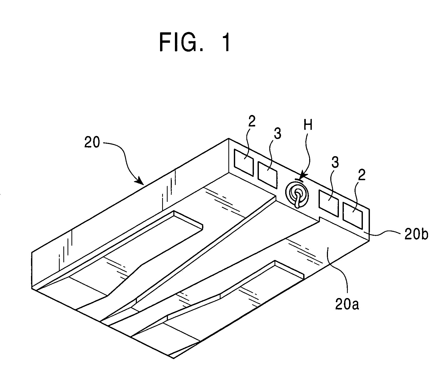
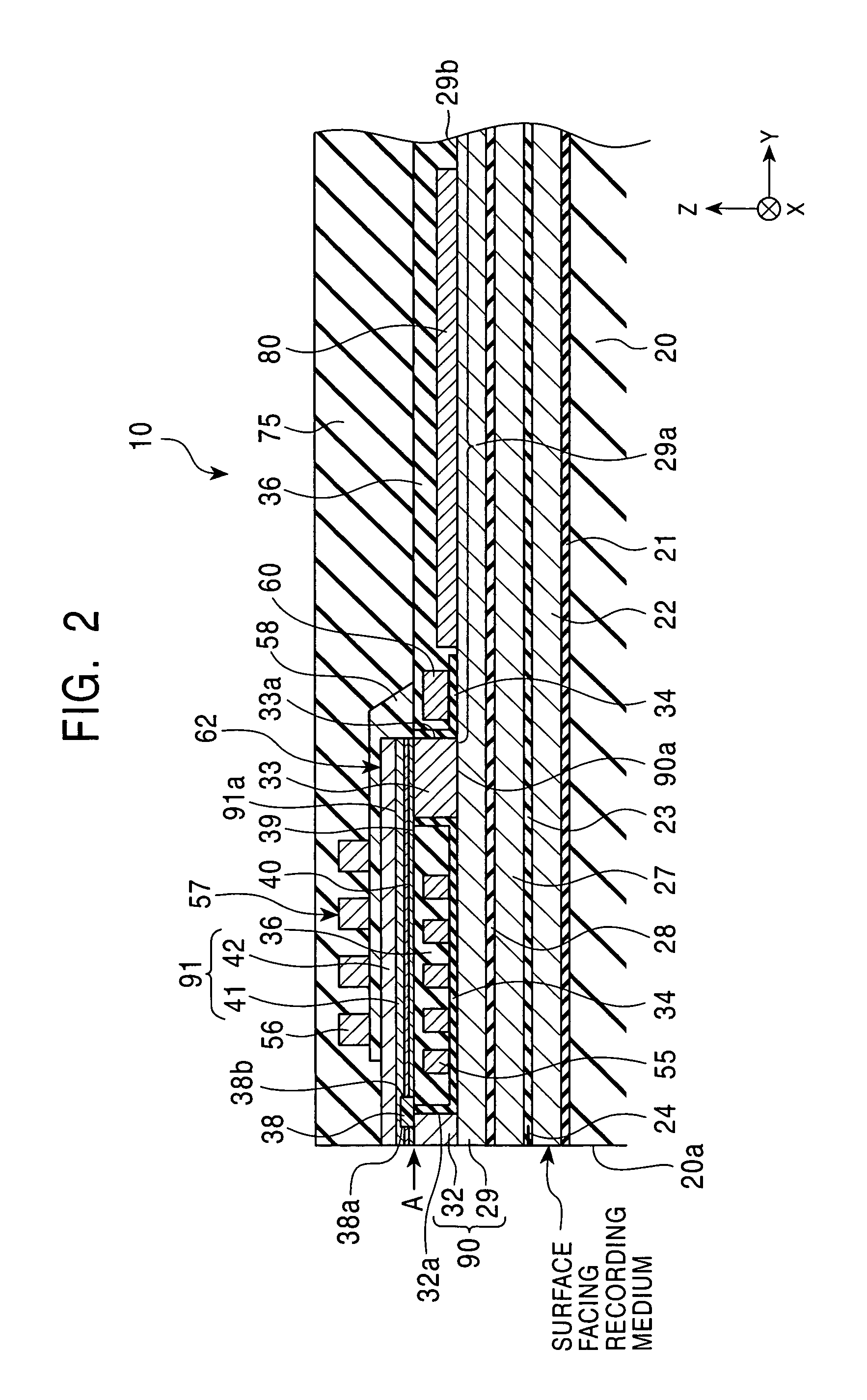
[0050]FIG. 1 is a perspective view showing an entire slider provided with a thin film magnetic head according to the present invention; FIG. 2 is a partial vertical cross-sectional view showing the structure of a thin film magnetic head of a first embodiment according to the present invention; and FIGS. 3 and 4 are partial plan views each showing the thin film magnetic head shown in FIG. 2.

[0051]In the present invention, the X direction shown in the figure is called a “track width direction”, and the Y direction in the figure is called a “height direction”. In addition, the Z direction in the figure is a traveling direction of a recording medium (magnetic disc). In the present invention, the front end surface (the leftmost surface in FIG. 2) of the thin film magnetic head is called a “surface facing a recording medium”. In addition, in individual layers, a “front end surface (front end portion)” indicates the surface at the left side in FIG. 2, and a “back end surface (back end port...

second embodiment

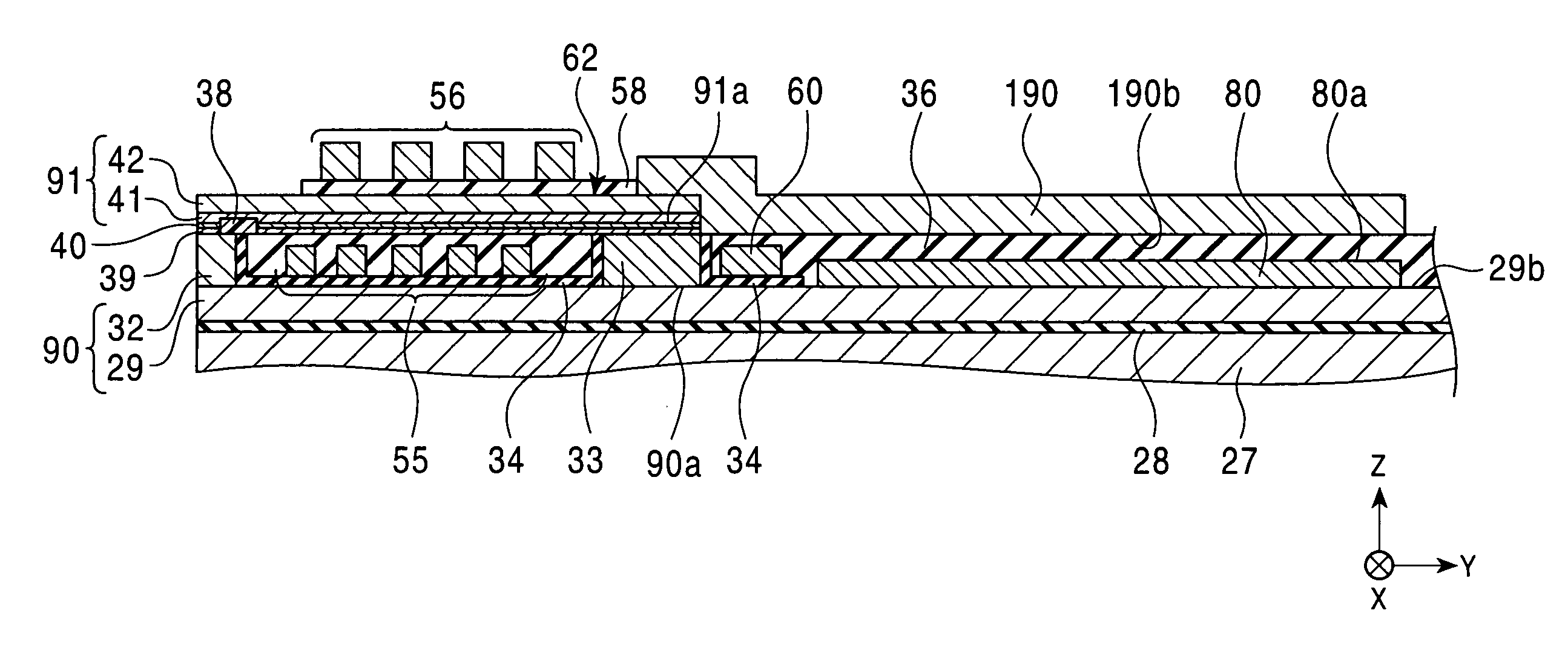
[0098]FIG. 5 is a partial vertical cross-sectional view showing the structure of a thin film magnetic head of a second embodiment according to the present invention and corresponds to FIG. 2. FIG. 6 is a partial plan view of the thin film magnetic head shown in FIG. 5 and corresponds to FIG. 4.

[0099]A thin film magnetic head 100 shown in FIGS. 5 and 6 has the structure approximately equivalent to that of the thin film magnetic head 10 shown in FIGS. 2 and 4. Accordingly, in the thin film magnetic head 100 shown in FIGS. 5 and 6, the same reference numerals of the thin film magnetic head 10 designate elements having the same structures as those of the thin film magnetic head 10, and descriptions thereof will be omitted.

[0100]In the thin film magnetic head 100 shown in FIGS. 5 and 6, unlike the thin film magnetic head 10 shown in FIGS. 2 and 4, a second metal layer 190 is provided so as to extend over a part of the upper surface 42a of the upper core layer 42 to the coil insulating la...

third embodiment

[0111]FIG. 7 is a partial vertical cross-sectional view showing the structure of a thin film magnetic head of a third embodiment according to the present invention and corresponds to FIG. 2. FIG. 8 is a partial plan view of the thin film magnetic head shown in FIG. 7 and corresponds to FIG. 4.

[0112]A thin film magnetic head 200 shown in FIGS. 7 and 8 has the structure approximately equivalent to that of the thin film magnetic head 100 shown in FIGS. 5 and 6. Accordingly, in the thin film magnetic head 200 shown in FIGS. 7 and 8, the same reference numerals of the thin film magnetic head 100 designate elements having the same structures as those of the thin film magnetic head 100, and descriptions thereof will be omitted.

[0113]Unlike the thin film magnetic head 100 shown in FIGS. 5 and 6, in the thin film magnetic head 200 shown in FIGS. 7 and 8, an upper surface 80a of the first metal layer 80 and a lower surface 190b of the second metal layer 190 are electrically connected to each ...


PUM

PropertyMeasurementUnit
Electrical conductoraaaaaaaaaa
Heightaaaaaaaaaa
Magnetismaaaaaaaaaa

Abstract

A method for manufacturing a thin film magnetic head comprises forming a first magnetic core extending from a surface facing a recording medium in a height direction. The method further comprises forming first coil pieces from a first conductive material on the coil insulating underlayer at a side of the surface facing the recording medium with respect to the connecting region, and simultaneously forming a first metal layer from said first conductive material on the first magnetic core in the back region located from the connecting region in the height direction. The method also comprises forming a coil insulating layer for covering the first coil pieces, and forming the second magnetic core above the first magnetic core. The method further comprises forming a toroidal coil layer, forming second coil pieces from a second conductive material on the insulating layer, and connecting the second coil pieces to the respective first coil pieces, and simultaneously with the formation of the second coil pieces, forming a second metal layer.

Description

[0001]This application claims the benefit of priority to Japanese Patent Application No. 2003-158756, herein incorporated by reference.BACKGROUND OF THE INVENTION[0002]1. Field of the Invention[0003]The present invention relates to recording thin film magnetic heads having a toroidal coil layer and used for floating type magnetic heads or the like, and more particularly, relates to a thin film magnetic head and a manufacturing method thereof, the thin film magnetic head having a large heat capacitance at a height direction side of a toroidal coil layer and superior heat dissipation properties.[0004]2. Description of the Related Art[0005]In recent years, concomitant with the trend toward higher recording density, miniaturization of recording thin film magnetic heads (inductive heads) having a core layer and a coil layer has increasingly advanced, and as a result, it has become necessary to coil a conductive material in a very small space for forming a coil layer.[0006]Accordingly, in...

Claims


Application Information

Patent Timeline
IPC IPC(8): G11B5/17G11B5/31G11B5/39G11B5/40
CPCB82Y10/00G11B5/313G11B5/3133G11B5/3136G11B5/40G11B5/3163Y10T29/49073G11B5/3967Y10T29/49062Y10T29/4906G11B5/3903
Inventor SATO, KIYOSHI
Owner TDK CORPARATION
Learn More