Video display apparatus for correcting luminance difference between display pixels
a technology of video display and luminance difference, which is applied in the field of video display apparatus, can solve the problems of suppressing luminance or contrast, irregular luminance of the display, and generating luminance irregularities, etc., and achieves the suppression of performance reduction, luminance reduction, and irregular luminance correction
- Summary
- Abstract
- Description
- Claims
- Application Information
AI Technical Summary
Benefits of technology
Problems solved by technology
Method used
Image
Examples
embodiment 1
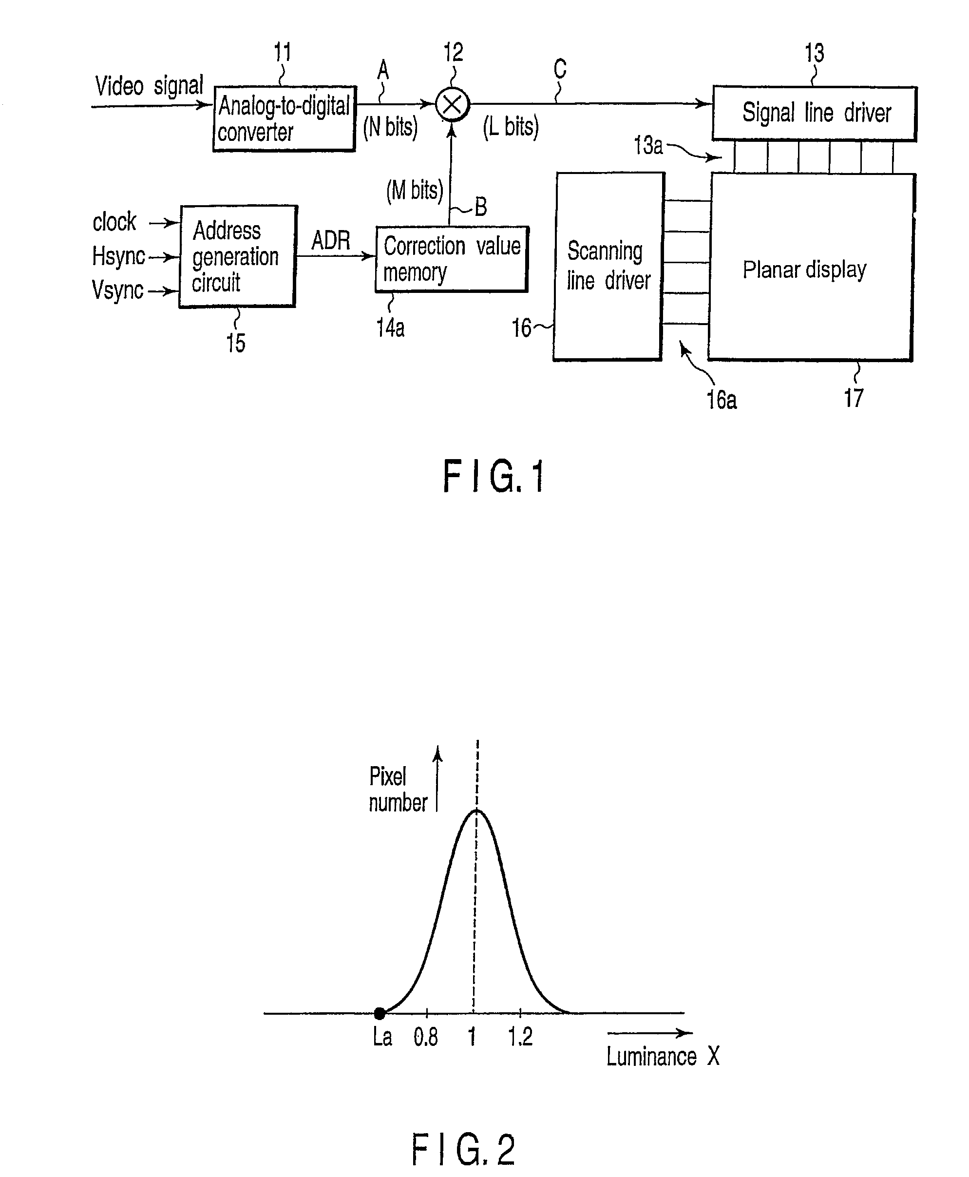
[0027]FIG. 1 is a block diagram illustrating a video display apparatus according to the first embodiment of the present invention.
[0028]Reference numeral 11 denotes an analog-to-digital converter; reference numeral 12, a multiplier; reference numeral 13, a signal line drive circuit; reference numeral 14a, a correction value memory; reference numeral 15, an address generation circuit; reference numeral 16, a scanning line drive circuit; and reference numeral 17, a planar display. It is to be noted that a field emission display (FED), an electroluminescent display, a liquid crystal, a plasma display or the like is used as the planar display 17. A video image is displayed in this planar display 17 based on a video signal subjected to processing described below. Further, the analog-to-digital converter 11 is a converter which converts an analog signal into a digital signal, and comprises a semiconductor IC or the like.
[0029]When a broadcast signal is received through a non-illustrated b...
embodiment 2
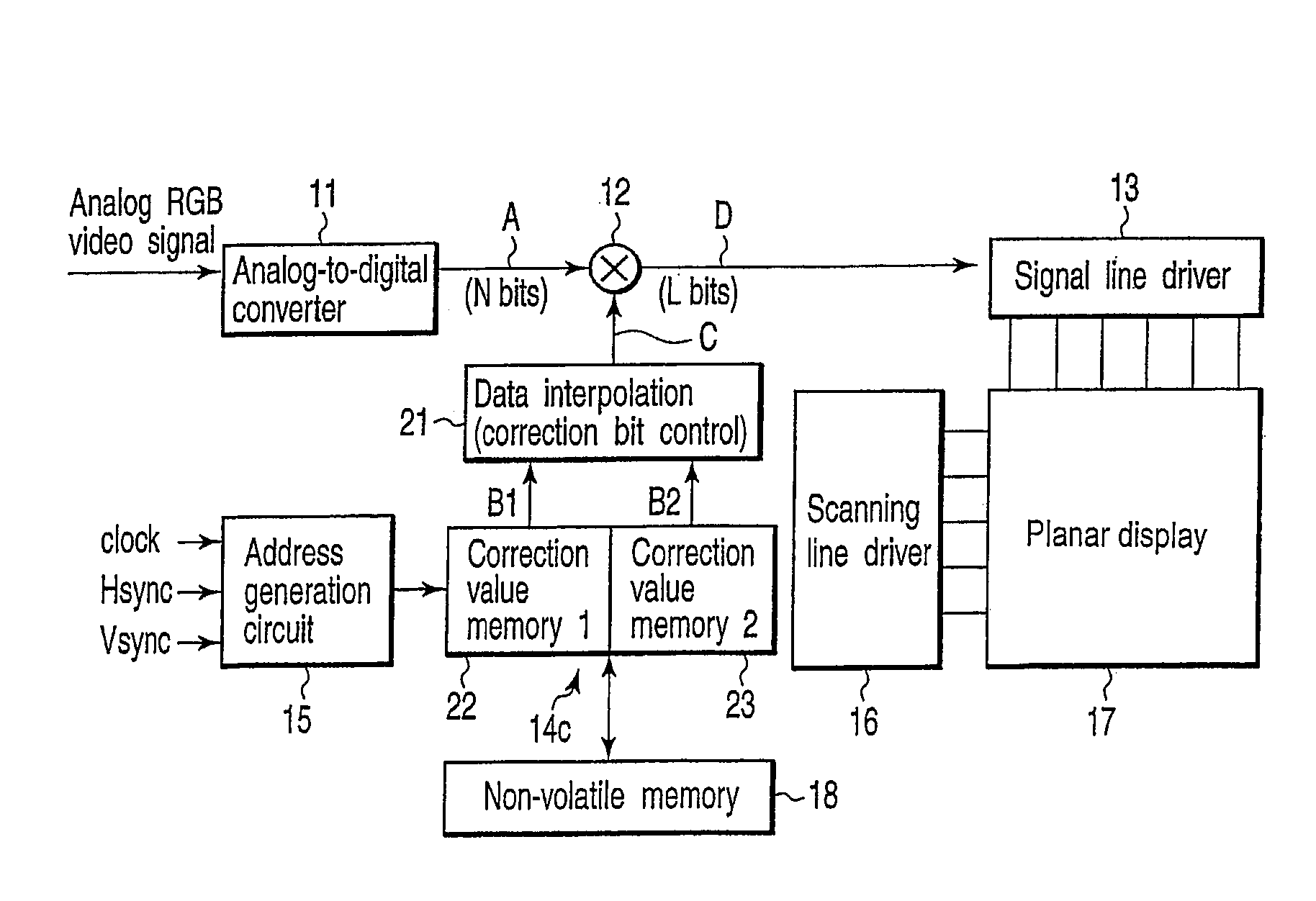
[0057]A second embodiment according to the present invention will now be described. FIG. 5 is a block diagram showing a structure of the second embodiment. Like reference numerals denote structures equivalent to those in the foregoing embodiment, thereby eliminating the explanation.
[0058]Reference numeral 21 denotes a data interpolation portion according to the second embodiment. The data interpolation portion 21 has a correction bit control portion added to the data interpolation portion 20 in the first embodiment.
[0059]The data interpolation portion (the correction bit control portion) 21 outputs from a correction value memory 14b data consisting of M bits by using correction data consisting of P bits which is used to correct, especially, the difference in luminance characteristics between display pixels in a planar display.
[0060]The data interpolation portion 21 according to the second embodiment “selectively” interpolates the correction data B consisting of P bits output from th...
embodiment 3
[0075]A third embodiment according to the present invention will now be described. FIG. 7 is a view illustrating a scheme of the third embodiment.
[0076]In this embodiment, correction data which is used to correct the difference in luminance between display pixels in a planar display 17 is divided into two or more types of data having different bit numbers and stored in the divided state. For example, the sensitivity of the human eye is high at the central portion 17b rather than a peripheral portion 17a of the display 17 (it is sensitive to irregularities in luminance at the central portion). Therefore, the information quantity at the central portion 17b is increased, and the information quantity at the periphery 17a is reduced. For example, correction data at the central portion 17b is determined as data consisting of six bits (a first bit number) and correction data at its periphery 17a is determined as data consisting of four bits (a second bit number), and these sets of data are...
PUM
 Abstract
Description
Claims
Application Information
 - R&D
- Intellectual Property
- Life Sciences
- Materials
- Tech Scout
- Unparalleled Data Quality
- Higher Quality Content
- 60% Fewer Hallucinations
Browse by: Latest US Patents, China's latest patents, Technical Efficacy Thesaurus, Application Domain, Technology Topic, Popular Technical Reports.
© 2025 PatSnap. All rights reserved.Legal|Privacy policy|Modern Slavery Act Transparency Statement|Sitemap|About US| Contact US: help@patsnap.com


