
A-pillar structure for an automotive vehicle

a technology for automotive vehicles and a-pillars, which is applied in the direction of roofs, transportation and packaging, vehicle arrangements, etc., can solve the problems of conflicting design requirements of automobile designers, restrictive traditional flange formation and welding, and reduce the size of a-pillars, and reduce the effect of a-pillars

Inactive Publication Date: 2008-03-18
FORD GLOBAL TECH LLC
View PDF1 Cites 75 Cited by
  • Summary
  • Abstract
  • Description
  • Claims
  • Application Information

AI Technical Summary

Benefits of technology

[0010]It is an advantage of this invention that the strength of the A-pillar is substantially increased over conventional A-pillar design.
[0011]It is another advantage of this invention that the dimensions for maintaining binocular vision for the vehicle operator are not exceeded.

Problems solved by technology

Thus, the designers of automobiles are faced with conflicting requirements with respect to the design of the A-pillars.
To achieve maximum cross-section of a tubular inner member for an A-pillar body structure, while maintaining acceptable binocular vision standards, a traditional flange formation and welding is restrictive.

Method used


Image

  • A-pillar structure for an automotive vehicle
  • A-pillar structure for an automotive vehicle
  • A-pillar structure for an automotive vehicle

Examples


Embodiment Construction

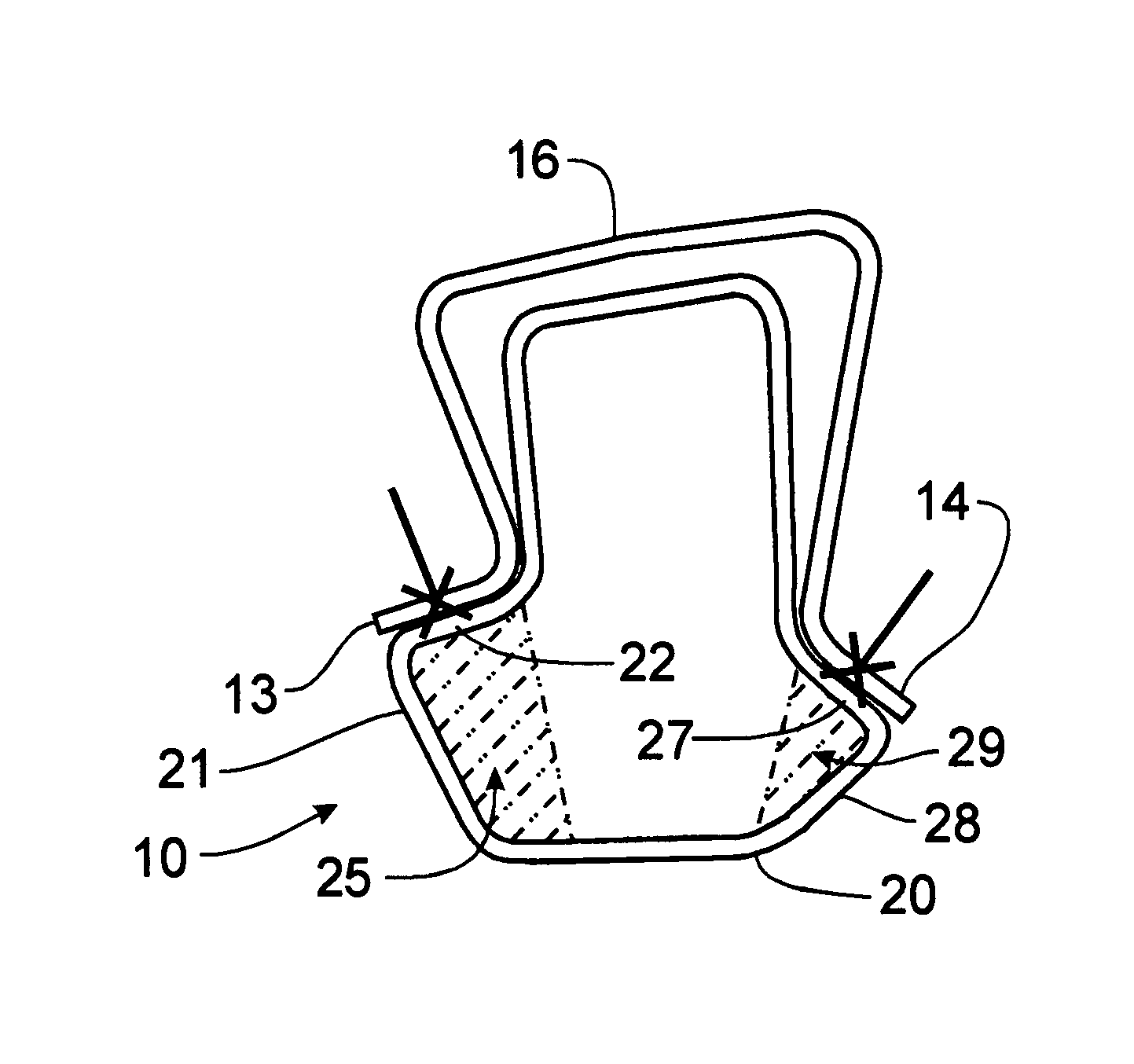
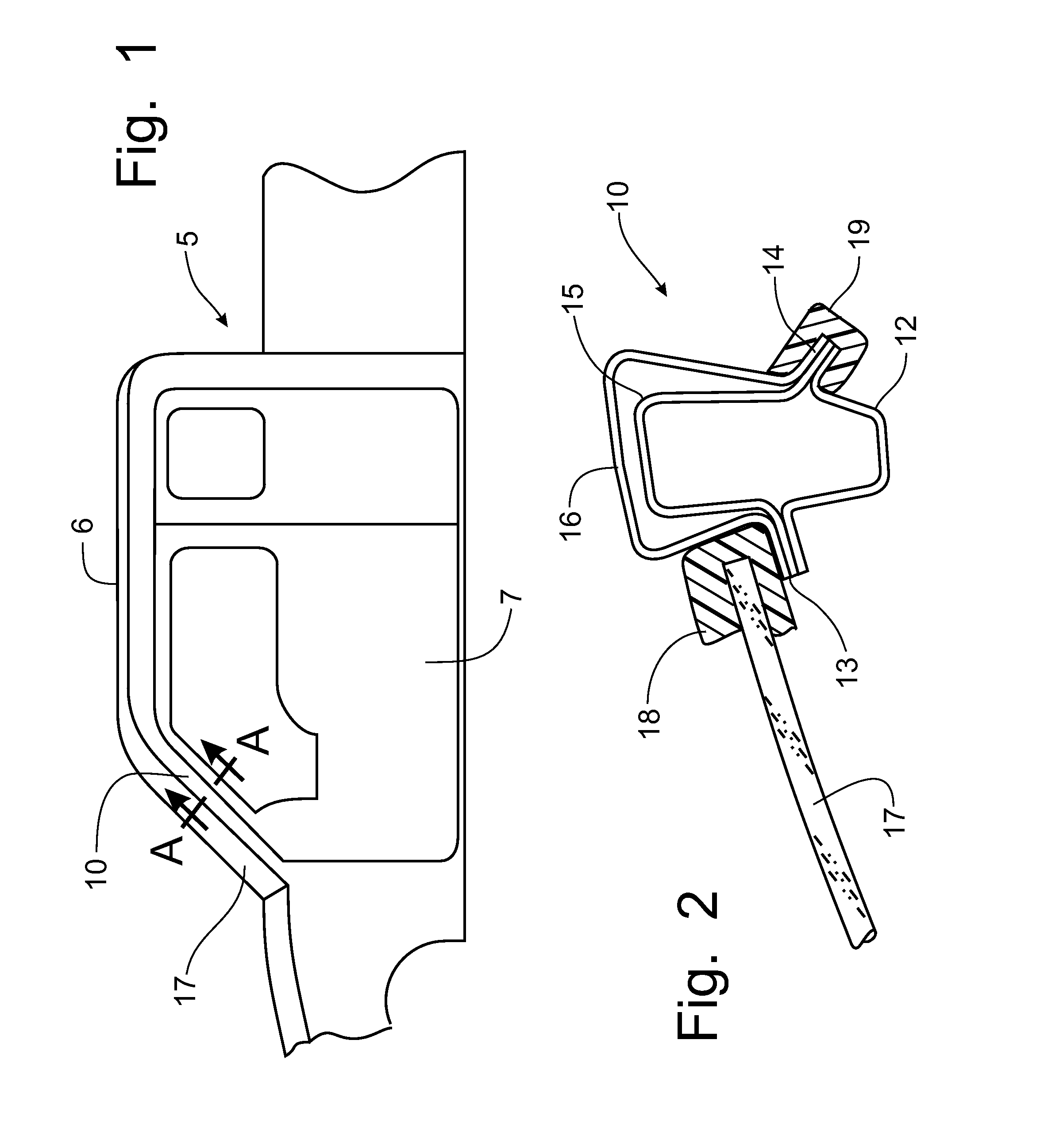
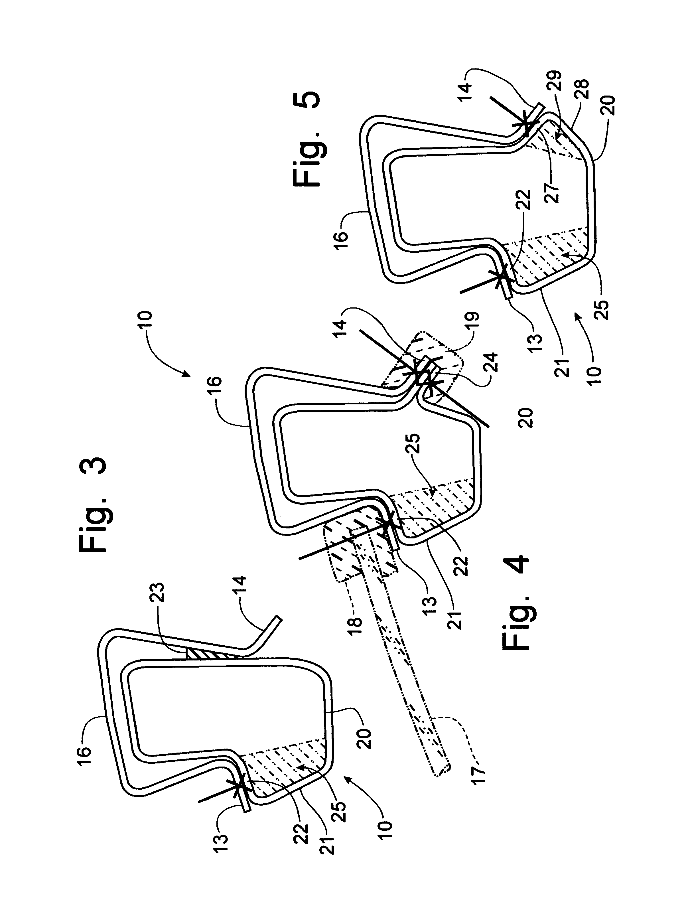
[0022]Referring to FIGS. 1-5, an A-pillar structure for an automotive vehicle incorporating the principles of the instant invention can best be seen. The automotive vehicle 5 is formed with an A-pillar 10 that supports the roof 6, the front door 7 and the windshield 17. FIG. 2 is a depiction of the conventional prior art A-pillar structure over which the instant invention represents an improvement. The conventional A-pillar structure is reflected in FIG. 2, which is a cross-sectional view of the A-pillar corresponding to lines A-A of FIG. 1. The A-pillar 10 is formed of a shaped inner member 12 that is formed with opposing vertically extending flanges. A reinforcement member 15 having mating flanges is welded at the flanges to the outer side of the inner member 12 to form a generally vertically extending beam 10. The door opening panel 16 is also formed with mating flanges that are welded to the flanges of the reinforcement member 15. The door opening panel 16 provides a uniform sur...


PUM


Abstract

An A-pillar structure on an automotive vehicle is manufactured from a formed tubular member that replaces the conventional inner and inner reinforcement members. The door opening panel is formed with conventional flanges that are welded or adhered to the tubular member to provide a conventional uniform surface against which the windshield and front door seals can be supported. The door opening panel flanges can be welded by one-sided welding techniques, such as laser stitch welding, to the tubular member. As an option, the movement of the front door seal from the ab flange to the front door can provide an opportunity to form the tubular member with a still larger cross-section for enhanced strength. The distance dimension spanning the opposing flanges to define the standard arc for maintaining binocular vision is retained while increasing the strength of the A-pillar due to the enlarged cross-sectional configuration provided by the tubular member.

Description

FIELD OF THE INVENTION[0001]This invention relates generally to an A-pillar on an automotive vehicle and, more particularly, to a structural configuration that will maximize the cross-sectional configuration while maintaining binocular vision for the operator of the vehicle.BACKGROUND OF THE INVENTION[0002]The A-pillars on an automotive vehicle are the structural members of an automotive frame positioned between the windshield and the front doors. The A-pillars support the roof structure as well and, therefore, must provide substantial support in rollover events. At the same time, the A-pillar lies within the sight lines of the operator and needs to have a minimal profile to allow the operator to maintain binocular vision with respect to the A-pillar. Thus, the designers of automobiles are faced with conflicting requirements with respect to the design of the A-pillars. To provide a strong structural member, the A-pillar needs to have a maximum cross-sectional configuration, yet main...

Claims


Application Information

Patent Timeline
IPC IPC(8): B62D25/00
CPCB62D25/04
Inventor HAUSLER, HENRYREED, JOHN
Owner FORD GLOBAL TECH LLC
Learn More