
Motor vehicle roof with a control means for electrical motor vehicle components and process for operating electrical motor vehicle components

a technology for motor vehicles and control means, applied in the direction of roofs, superstructure subunits, door/window fittings, etc., can solve the problems of distracting the driver, difficult to arrange the control within sight of the driver, and consuming a lot of time to choose the control function

Active Publication Date: 2008-03-11
WEBASTO AG
View PDF16 Cites 86 Cited by
  • Summary
  • Abstract
  • Description
  • Claims
  • Application Information

AI Technical Summary

Benefits of technology

[0015]A primary object of this invention is to provide a control means which can be comfortably actuated and a comfortable process for operation of at least one electrical component of a motor vehicle.

Problems solved by technology

With the increasing comfort in modern motor vehicles and the associated rise in the number of control functions to be performed, the arrangement of controls within sight of the driver has become more and more difficult for reasons of space.
The disadvantage here is that this choice of control functions is rather time-consuming, and thus, unduly distracts the driver.
The disadvantage here is that the operation easily distracts the driver and so-called “blind operation” is difficult or requires a corresponding routine of the operator.
In the known controls, the function of which is based on pressing, pulling or turning an actuating element, it is furthermore a disadvantage that these controls are subject to more or less extensive wear of the mechanical parts.
Moreover, the arrangement of individual controls or control assemblies has the disadvantage that variance of the vehicle equipment (for example, with or without a sliding roof, with or without outside mirror adjustment, etc.) entails a corresponding variance of the corresponding interior panel parts or consoles which are designed for housing these controls or the combination of controls which is desired for the special vehicle model.
Finally, for the operation of a control which is to be mechanically actuated, in the dark, it is difficult to find the control, mainly if it is not lighted and / or it is out of direct sight of the operator.
In this connection, it is noted that permanent lighting (also for example, background lighting) of controls in the dark is often perceived as disturbing by vehicle passengers.

Method used


Image

  • Motor vehicle roof with a control means for electrical motor vehicle components and process for operating electrical motor vehicle components
  • Motor vehicle roof with a control means for electrical motor vehicle components and process for operating electrical motor vehicle components
  • Motor vehicle roof with a control means for electrical motor vehicle components and process for operating electrical motor vehicle components

Examples


Embodiment Construction

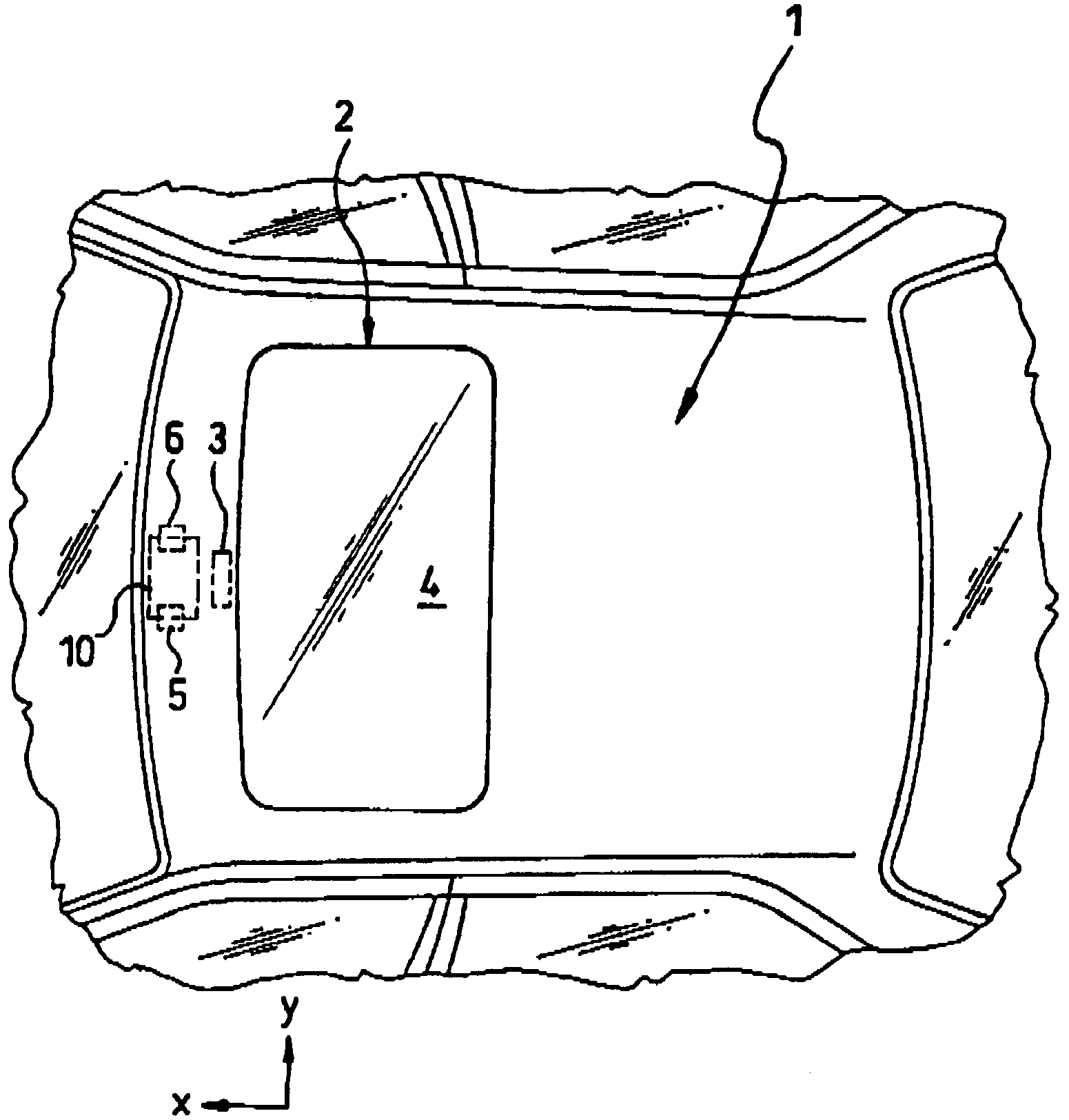
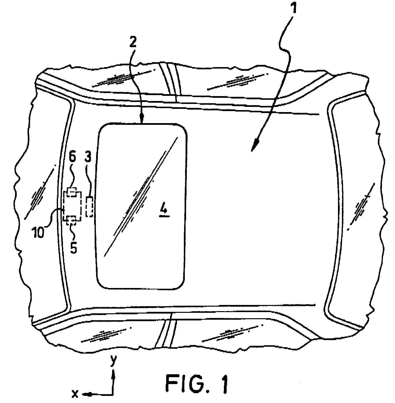
[0050]FIG. 1 shows the roof 1 of a motor vehicle with a sliding roof 2 which can be actuated in the conventional manner by means of an electric drive 3 for opening and closing of the roof opening by means of a sliding cover 4. Furthermore, the figure shows a left interior light 5 and a right interior light 6 which in the conventional manner are located on the underside of the vehicle roof 1 between the front roof edge and the roof opening.

[0051]In the figure, the directions to which reference is made below are drawn in, specifically, the lengthwise direction x of the motor vehicle, the transverse direction y and the vertical direction z of the motor vehicle.

[0052]The sliding roof 2 and its electric drive 3 and the interior lights 5, 6 are components of the vehicle electrical system which can be triggered by a control means 10 which is likewise located on the underside of the vehicle roof 1. For this purpose, the control means 10 comprises a sensor surface arrangement which is expose...


PUM


Abstract

A motor vehicle roof with a control for comfortable operation of at least one motor vehicle component by a passenger of the vehicle, the control having a sensor surface arrangement (12g) for detecting the presence and / or movement of the hand or part of the hand of the passenger in a detection area of the sensor surface arrangement (12g). The sensor surface arrangement (12g) provides an electrical trigger signal based on detection of the presence and / or movement of at least part of the hand for triggering the vehicle component(s).

Description

BACKGROUND OF THE INVENTION [0001]1. Field of the Invention[0002]This invention relates to a motor vehicle roof with a control means for operating at least one electrical motor vehicle component by a passenger of the vehicle and a corresponding process for operation of at least one electrical vehicle component.[0003]2. Description of Related Art[0004]The interior of modern motor vehicles generally houses a host of electrical controls which must be manually actuated by the driver or by passengers of the vehicle to operate motor vehicle components (for example, slide switches, rotary switches or pushbuttons).[0005]Controls which are considered especially important in practice (for example, for the headlights, windshield wipers, etc.) must generally be located within the immediate visual range of the driver, i.e., in the area of the vehicle interior which the driver can easily survey while driving “with a glance forward” without greater distraction from ambient events and which lies wi...

Claims


Application Information

Patent Timeline
IPC IPC(8): B60Q1/00B60J7/057B60Q3/02
CPCB60J7/057B60Q3/0296E05Y2400/86E05Y2900/542E05F15/00E05Y2400/852B60Q3/82
Inventor JOEHL, ANTONKLESING, JOACHIMRUDOLPH, THOMASEDER, MICHAEL
Owner WEBASTO AG
Learn More