
Antenna for mobile communication terminals

a mobile communication terminal and antenna technology, applied in the field of radio frequency antennas, can solve the problem that the pifa pair of slotted antennas is less effective for telecommunications handsets whose covers are covered

Active Publication Date: 2008-03-04
RPX CORP
View PDF7 Cites 73 Cited by
  • Summary
  • Abstract
  • Description
  • Claims
  • Application Information

AI Technical Summary

Benefits of technology

The present invention provides an antenna for a mobile communication terminal that includes a first ground plate and a first resonator positioned in a parallel plane to the first ground plate. The antenna also includes a second ground plate and a second resonator positioned in a parallel plane to the first ground plate. The first and second resonators are connected to the first and second ground plates, respectively, through connectors. The first and second ground plates are connected to the receiver and transmitter means through antenna feeding means. The technical effect of this invention is to provide an improved antenna design that allows for better signal transmission and reception in a mobile communication terminal.

Problems solved by technology

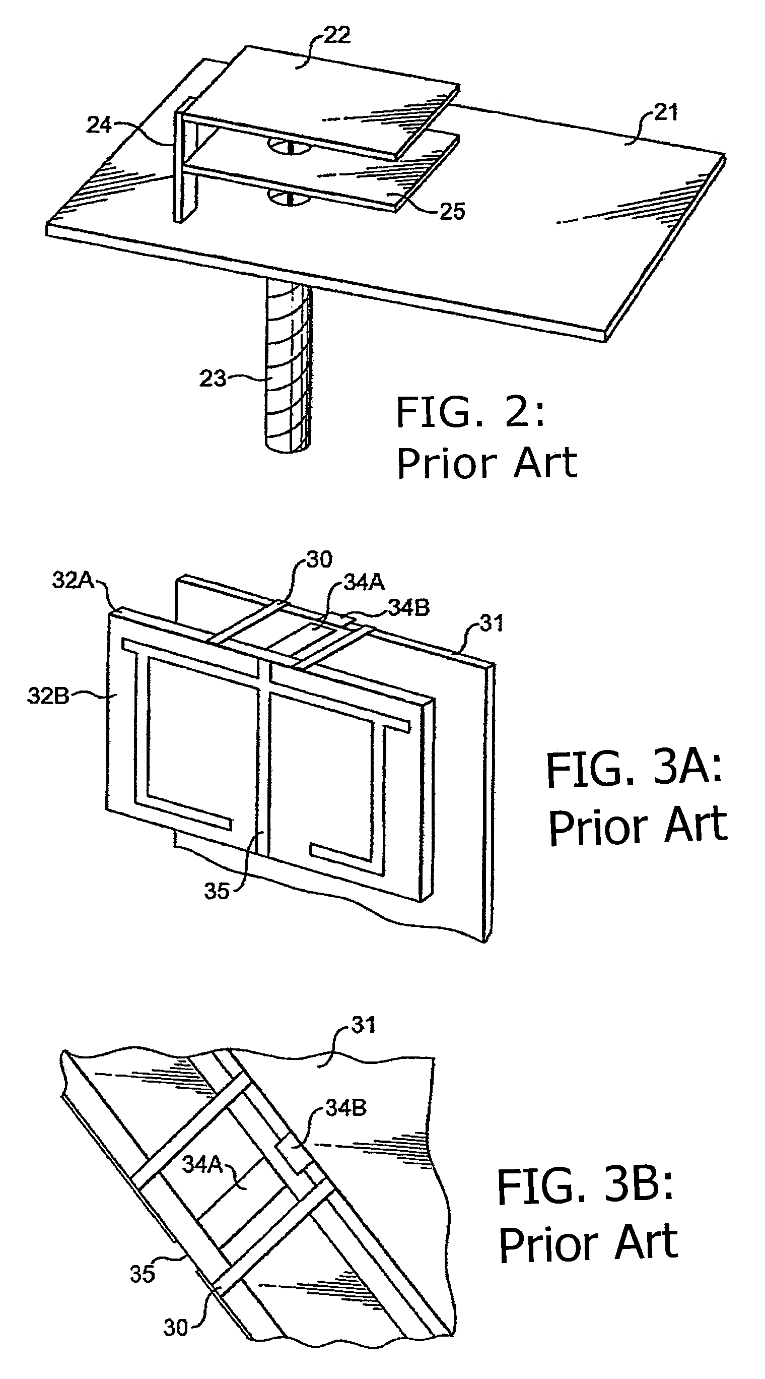
It has been found that such a slotted PIFA pair antenna is less effective for telecommunications handsets whose covers are made substantially of metal.

Method used


Image

  • Antenna for mobile communication terminals
  • Antenna for mobile communication terminals
  • Antenna for mobile communication terminals

Examples


Embodiment Construction

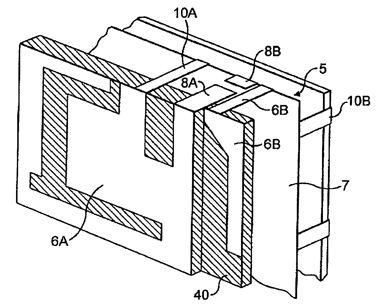
[0022]The inventors of the present invention have found that significant improvements in antenna performance may be achieved, compared with a standard PIFA, by introducing an additional ground plane between the ground plane 1 of FIG. 1A and the conducting sheet 2.

[0023]In general, if two or more ground connections are made between a conducting plate and ground, then the plate will act as an additional ground plane rather than as a parasitic resonator such as that shown as 25 in the prior art structure illustrated in FIG. 2. As discussed further below, the positions of the ground connections affect the frequency at which the additional ground plane will provide resonance.

[0024]An exemplary arrangement is shown in FIG. 4A, where a circuit board (for example, a printed wiring board) 5 acts as the antenna's main ground plane. Alternatively, an RF shielding can or any metal part of mobile handset may be used in place of the printed wiring board (PWB) as the antenna's ground plane. Positi...


PUM


Abstract

An antenna including: a first substantially planar ground plate; a first substantially planar resonator positioned in a plane substantially parallel to the first ground plate; a second substantially planar ground plate positioned in a plane substantially parallel to the first ground plate; two or more connectors for electrically connecting the second ground plate to ground; and one or more connectors for electrically connecting the first resonator to the second ground plate; wherein the first resonator and the second ground plate are connected to at least one of receiver means and transmitter means by antenna feeding means.

Description

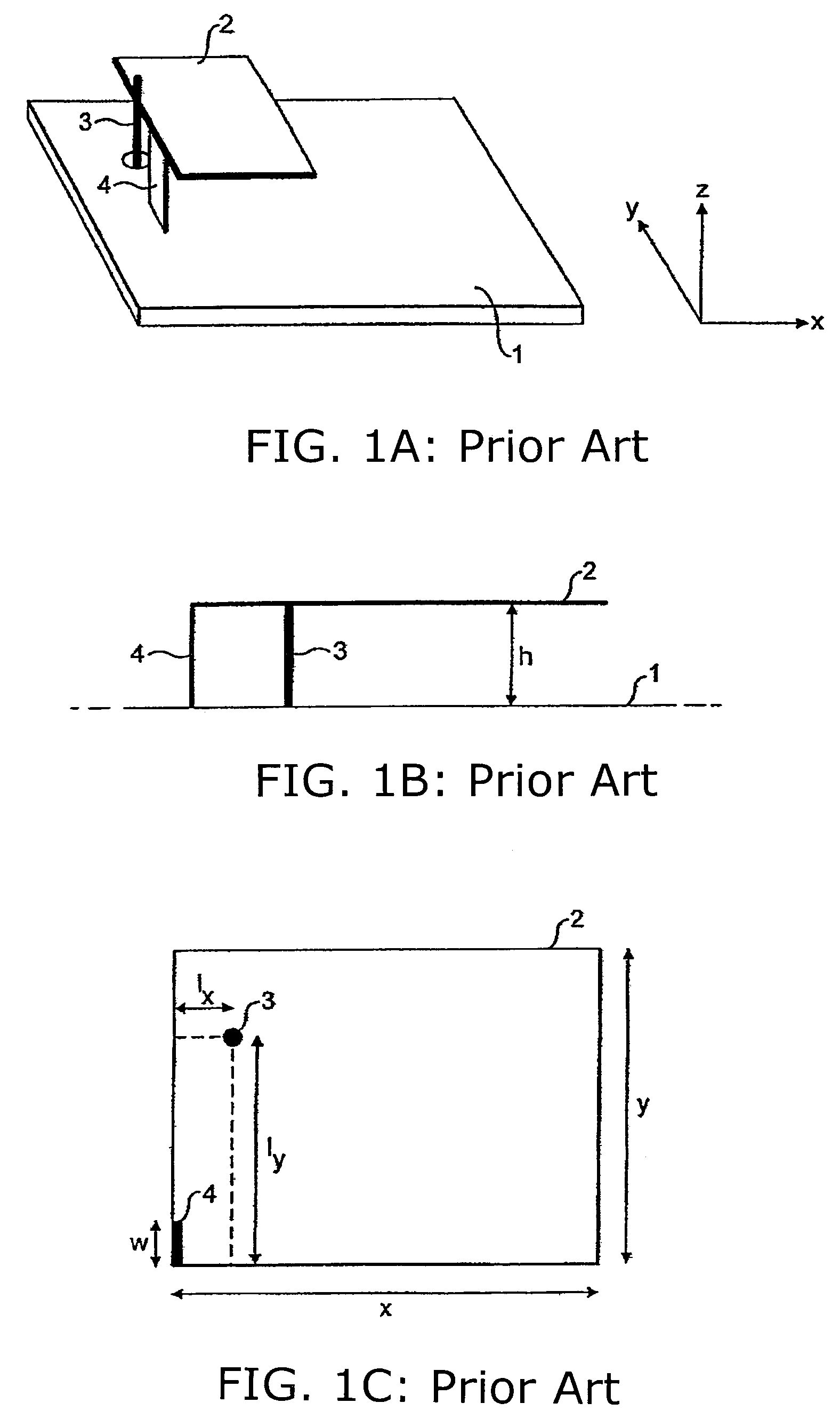
[0001]This application claims priority to GB 0330052.2 filed on Dec. 24, 2003.FIELD OF INVENTION [0002]The present invention relates to radio frequency antennas for use in mobile communication terminals. More particularly, it relates to providing multiple-band resonances and / or wider bandwidth resonances in mobile terminals.BACKGROUND OF THE INVENTION [0003]It is known in the field of mobile communications to use PIFA's (planar inverted-F antennas) to achieve a relatively large bandwidth at particular frequencies that may be used for the transmission and reception of mobile communications. Such a prior art PIFA is shown in FIG. 1. FIG. 1A shows a ground plane 1 with a conducting plate 2 mounted above it by means of a short circuit plate 4. FIG. 1B shows a side view of the PIFA and FIG. 1C shows a top view of the conducting plate 2. The frequencies at which a PIFA produces resonances, and the bandwidths of generated frequencies depend on the geometry of the PIFA. Relevant parameters ...

Claims


Application Information

Patent Timeline
Patent Type & Authority Patents(United States)
IPC IPC(8): H01Q1/38H01Q1/48H01Q19/00H01Q1/24H01Q5/00H01Q5/371H01Q5/378H01Q9/04
CPCH01Q1/243H01Q9/0414H01Q9/0421H01Q5/378H01Q19/005H01Q5/371H01Q9/0442H01Q9/0407
Inventor WANG, HANYANGWILLIAMS, STUART
Owner RPX CORP
Learn More