Apparatus and method for handling a crossover tube of a gas turbine

a technology for gas turbines and crossover tubes, applied in the direction of machines/engines, manufacturing tools, light and heating apparatus, etc., can solve the problems of time-consuming process, particularly difficult to effectively reach, engage and manipulate crossover tubes, and existing tools may or may not effectively engage, etc., to achieve effective and efficient engagement and manipulation

Inactive Publication Date: 2008-03-04
QUIROZ MARIO I
View PDF6 Cites 7 Cited by
  • Summary
  • Abstract
  • Description
  • Claims
  • Application Information

AI Technical Summary

Benefits of technology

[0007]The present invention provides a unique, new and useful structure and method that addresses the foregoing issues. The structure and method are designed to enable an operator to effectively and efficiently engage and manipulate a crossover tube of a gas turbine.
[0008]Moreover, a preferred tool according to the present invention is designed to efficiently and securely engage and manipulate a crossover tube, including those crossover tubes that are particularly difficult to reach in a gas turbine.

Problems solved by technology

In the applicant's experience, handling such crossover tubes is a time consuming process that is often subject to “hit and miss” situations, in the sense that the existing tools known to applicant may or may not be capable of effectively engaging a crossover tube.
Specifically, existing tools may or may not effectively engage the crossover tube, or may slip off the crossover tube, so that it may take an operator a number of tries to effectively engage a crossover tube, and then manipulate the crossover tube.
Also, there are generally a few crossover tubes that are particularly difficult to effectively reach, engage and manipulate.
Thus, the 4 or so crossover tubes that have to be removed by the operator with a tool, before the operator can maneuver into the confines of the gas turbine to remove the other crossover tubes, are particularly challenging.

Method used


Image

  • Apparatus and method for handling a crossover tube of a gas turbine
  • Apparatus and method for handling a crossover tube of a gas turbine
  • Apparatus and method for handling a crossover tube of a gas turbine

Examples


Embodiment Construction

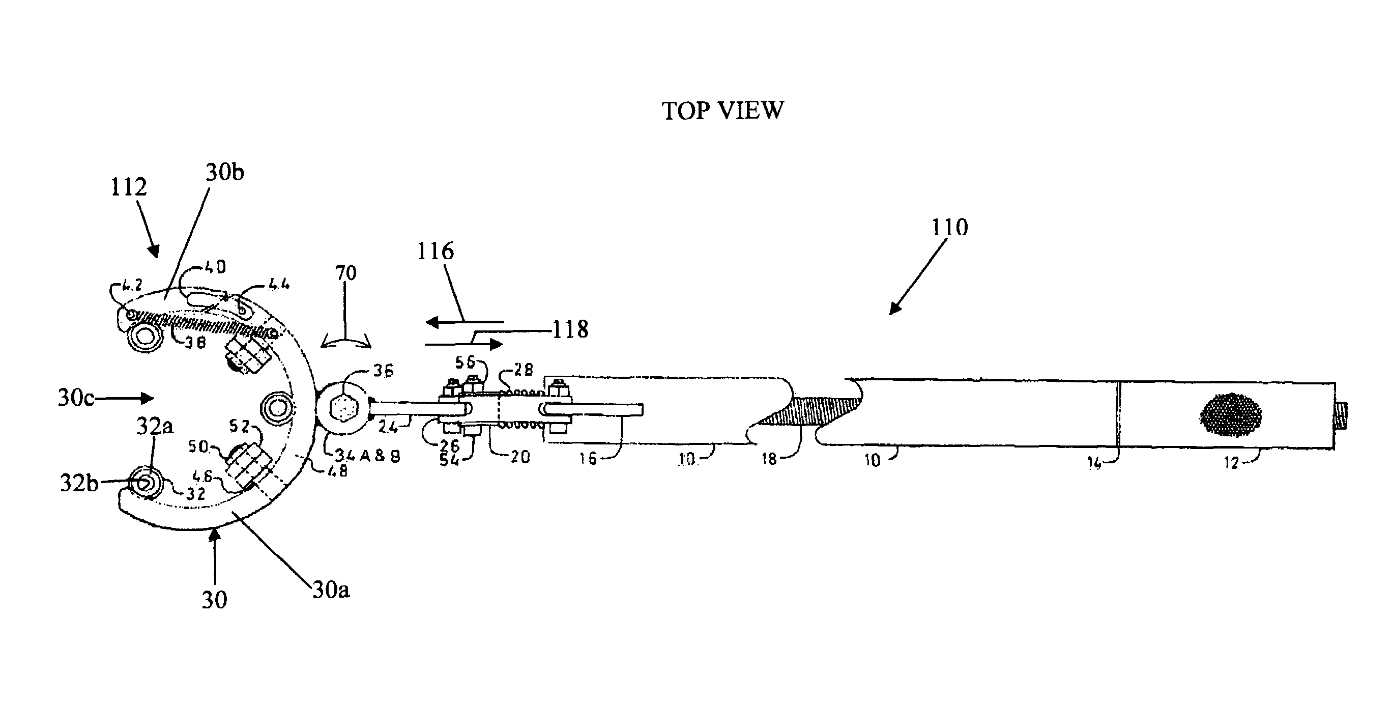
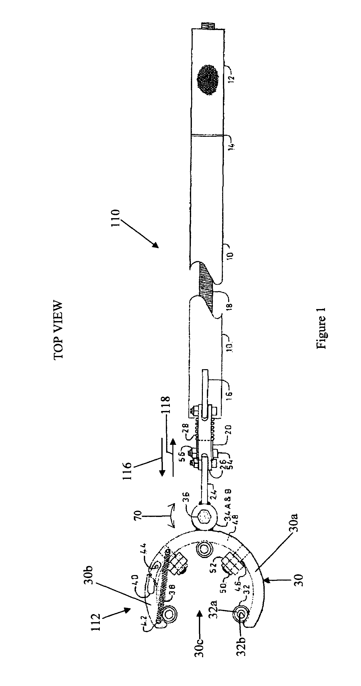
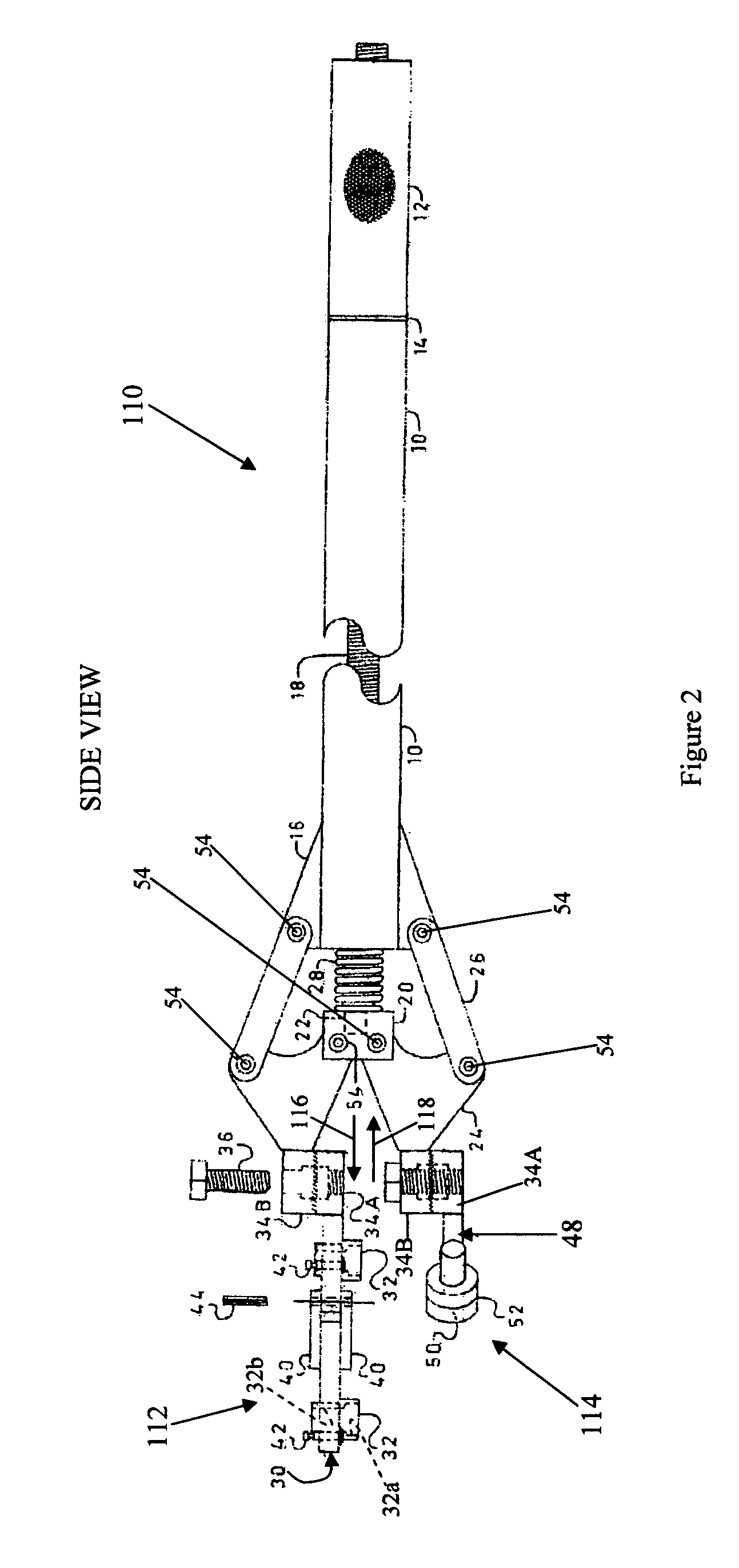
[0045]As discussed above, the present invention provides a structure and method that is designed to enable an operator to effectively and efficiently engage and manipulate a crossover tube of a gas turbine. The principles of the invention are described below in connection with a tool for a 501 B & D Frame Westinghouse gas turbine, but from that description, the manner in which a tool can be designed and operated to handle crossover tubes from various types of gas turbines.

[0046]FIGS. 23-25 illustrate a type of gas turbine 100 with which the principles of the present invention are particularly useful. The gas turbine 100 can be e.g. a 501 B & D Frame Westinghouse gas turbine of a type that is well known in the art. It includes an array of burner baskets 102 in which combustion takes place in the turbine. The burner baskets 102 have flanges 104 (FIG. 24), and crossover tubes 106 are connected to the burner baskets, and are effective to communicate flame between the burner baskets. The...


PUM

PropertyMeasurementUnit
reaction forceaaaaaaaaaa
timeaaaaaaaaaa
structureaaaaaaaaaa

Abstract

A unique, new and useful structure and method is provided for effectively and efficiently engaging and manipulating a crossover tube of a gas turbine. The tool is manipulated to a gripping position in which it securely engages the spring loaded locks of a crossover tube while applying a reaction force to a portion of the burner basket that is associated with the crossover tube, so that manipulating the handle manipulates the crossover tube that is engaged by the tool. A preferred version of the tool has specially designed structure for coupling a handle with the gripper and follower structure such that the tool can effectively and efficiently reach and manipulate crossover tubes that are in particularly difficult to reach areas of a gas turbine.

Description

BACKGROUND[0001]The present invention relates to apparatus and method for quickly and efficiently manipulating crossover tubes of a gas turbine. Crossover tubes are also known in this art as “crossflame” tubes.[0002]In a gas turbine, there are a number of crossover tubes that communicate gas between the combustors (also referred to a burner baskets) of the gas turbine. A crossover tube is generally supported on the flange of a burner basket. In a 501 B&D Westinghouse gas turbine, there may be 30 crossover tubes between the burner baskets.[0003]It is necessary to reach into the confines of the gas turbine, to handle the crossover tubes, in order to change the crossover tubes. Such handling requires that an operator reach into the confines of the gas turbine, to release the crossover tubes from their support on the burner baskets, and withdraw the crossover tubes from the turbine. In order to reinsert a new crossover tube, the tube must be manipulated to locate it in an appropriate po...

Claims


Application Information

Patent Timeline
Patent Type & Authority Patents(United States)
IPC IPC(8): B25B27/14
CPCB25B13/48F02C7/20Y10T29/53909F23R3/48
Inventor QUIROZ, MARIO I.
Owner QUIROZ MARIO I
Why Eureka
Try Eureka